
 Dr Rajesh Kumar Arora, Senior Manager (Technical), Design and Engineering, Delhi Transco Limited
A surge arrester is a protective device used on power distribution networks to limit overvoltage transients that can damage equipment and disrupt the flow of electricity. When surges occur, the arrester immediately limits, or clamps, the overvoltage condition by conducting the surge current to the ground. After the surge passes, the arrester returns to its initial state.
Selecting the best surge arrester will depend on several factors, including the specific application, the level of protection required, and the electrical system characteristics. Factors to consider when choosing a surge arrester include voltage rating, current rating, energy absorption rating, arrester type, response time, environmental conditions, certification and standards, and the manufacturer’s reputation.
This article sheds light on the voltage level to be selected for surge arresters based on the system earthing (grounding) configuration…
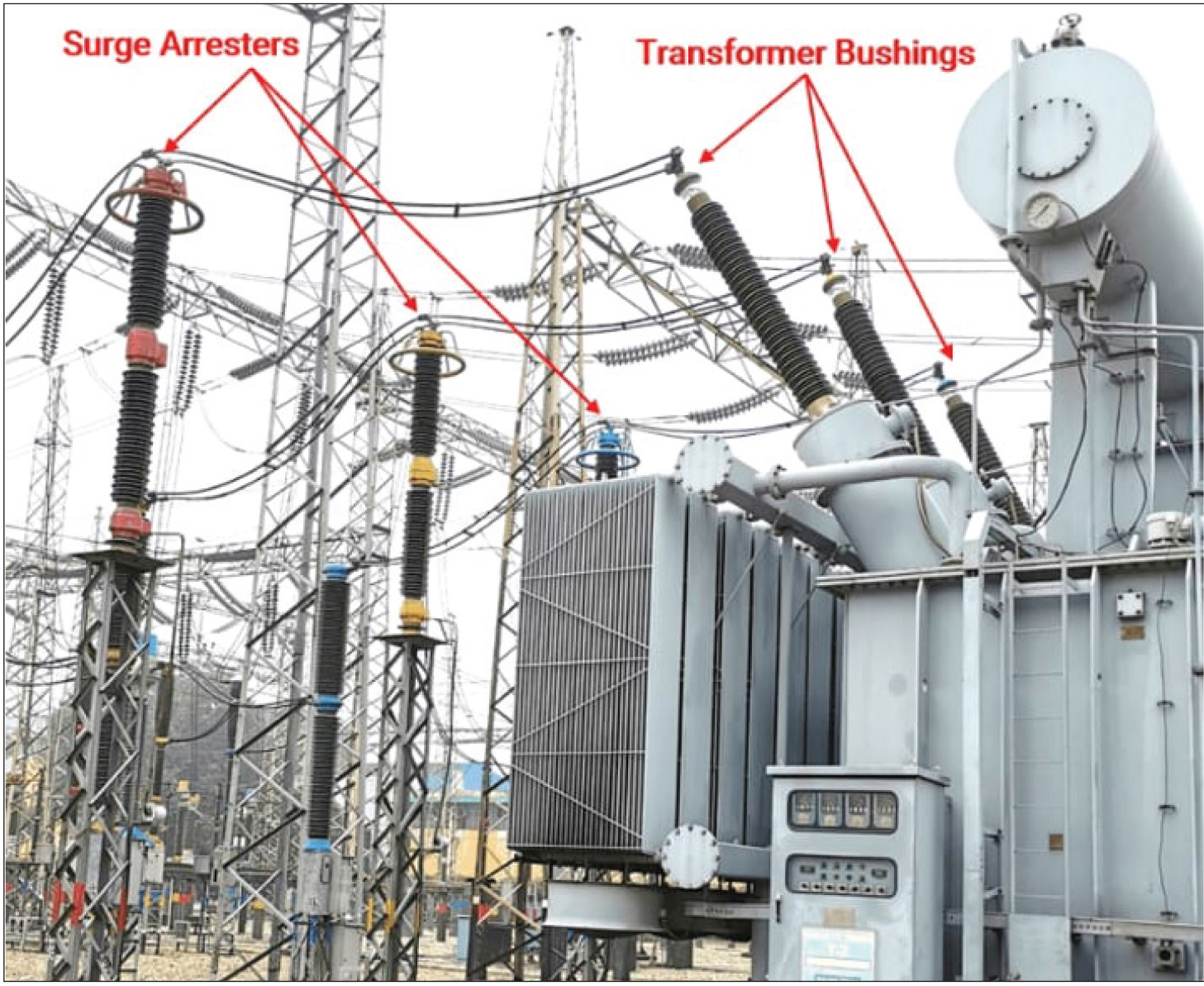
Surge arresters are voltage-limiting devices used to protect electrical insulation from voltage spikes (surges) in a power system. They protect the system from damage due to overvoltage conditions. (Refer Fig. 1)
In the past, surge arresters were called lightning arresters due to their primary function of protecting electrical insulation from lightning strikes on the system. The more generic term “surge arrester” now encompasses overvoltage conditions that can occur from numerous other sources, such as switching operations and ground faults.
Surge arrester working principle
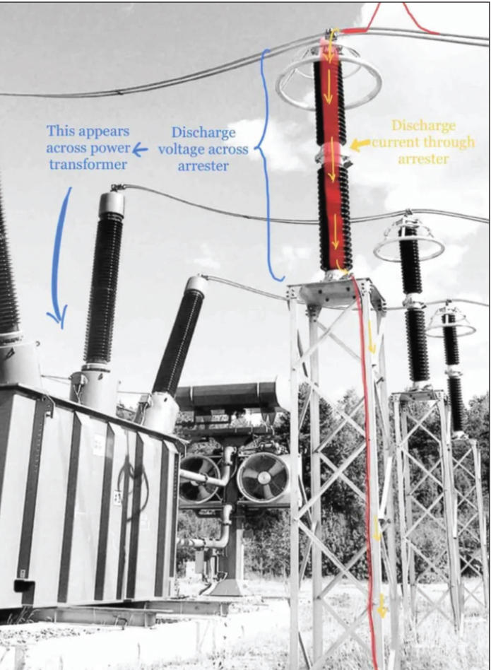
When a voltage surge travelling along the conductor reaches the point at which the lightning arrester is installed, it breaks down the insulation of the arrester momentarily, allowing the voltage surge to discharge to the ground. As soon as the system voltage drops below the predetermined value, the insulation between the conductor and the ground is restored, stopping any current flow to the ground. (Refer Fig. 2)
To perform this protective function satisfactorily, arresters must:
- Not allow current to flow to the ground as long as the system voltage remains normal.
- Provide a path to the ground when the system voltage rises to a predetermined value above normal, to dissipate the energy from the surge without raising the voltage at which the circuit is operating.
- Stop the flow of current to the ground as soon as the system voltage drops below the predetermined value, and restore the insulating qualities between the conductor and ground.
- Not be damaged by the discharge and be capable of automatically repeating the discharging process when required, in line with their energy rating and as per the operational duty test.
 The performance of an arrester is dependent on a good connection to the ground and will not function without a proper ground. The arrester should be placed as close as possible to the equipment that is to be protected, and the leads connecting arresters to the ground should be kept as short as possible and without any loops.
What exactly does a surge arrester do?
- It does not absorb lightning.
- It does not stop lightning.
- It diverts lightning to the ground.
- It clamps (limits) the voltage produced by lightning or switching.
- It only protects equipment electrically in parallel with it.

Surge arrester general selection criteria
The objective is to select the lowest-rated surge arrester that will adequately protect the equipment insulation and have a satisfactory service life when connected to the power system. The arrester with the minimum rating is preferred because it provides the greatest margin of protection for the insulation.
 A higher-rated arrester is better able to survive on a power system but provides a lower protective margin for a specific insulation level. Both arrester survival and equipment protection must be considered in arrester selection.
The class of lightning arrester to be applied depends on the importance and value of the protected equipment, its impulse insulation level and the expected discharge currents the arrester must withstand. Protection classes as per International Electromechanical Commisssion standards have been illustrated in Table 1.
Surge arrester voltage selection criteria
Once system voltages are understood, the next step in the selection process is to determine the system configuration to which the arrester will be applied. In other words, one must determine if it is a wye or delta system (star or delta). In addition, it is necessary to understand the role of the system neutral conductor in the circuit, if one is present. The power source transformer and the neutral bonding scheme determine how high the line-to-ground voltage of the unfaulted phases will rise during a ground fault. Fortunately, the number of system configurations is limited.

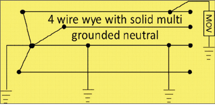
The most common configuration is the four-wire solid multi-grounded neutral as shown in Fig. 3. This is also known as an effectively grounded system.
A common and widely used industrial configuration is the three-wire impedance grounded wye (or star). The reason for its popularity is that the fault current to the earth is limited by impedance. Using low impedance can limit the fault current to levels that allow the use of lower-rated equipment in the system, resulting in cost savings. In cases of high impedance, a Petersen coil is used, providing fault-extinguishing capabilities without the need for breakers to break the fault. This is sometimes referred to as a resonant grounded system (shown in Fig. 4).
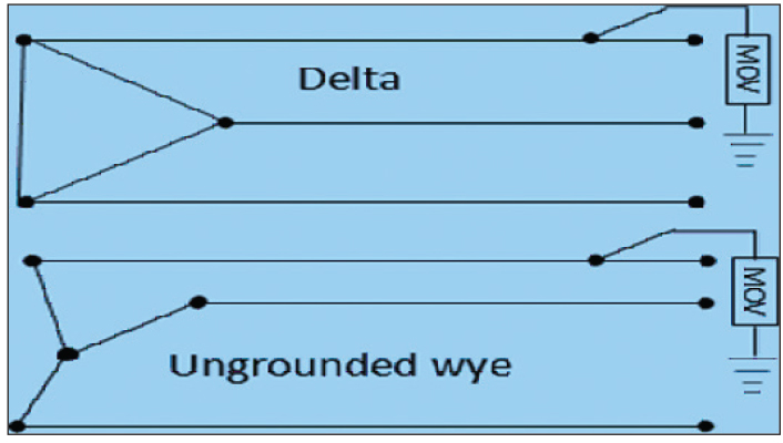
A third system configuration is the isolated or ungrounded system, which can be either delta- or wye-configured. Fig. 5 shows these two systems.
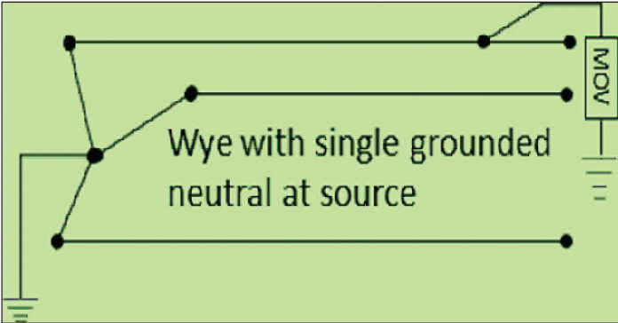
A common transmission line configuration is the single grounded wye, as shown in Fig. 6.
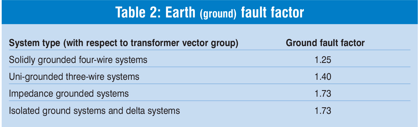
Table 2 lists the ground fault factors used to determine unfaulted phase voltage rise during a ground fault.
Note 1: Two factors may be used to measure this type of overvoltage:
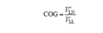
- Coefficient of grounding (COG):
- Earth fault factor (EFF):
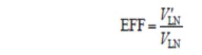
Where V’LN is the maximum phase-to-ground voltage on the unfaulted phases during a fault, and VLN and VLL are the nominal phase-to-neutral and phase-to-phase voltages respectively.
Hence, EFF = 1.73 COG.
Note 2: Mixed configurations
It is important to note that the grounding of the neutral at the source transformer is the configuration referred to when determining the voltage rise of the system.
For example, as seen in Figure 7, a delta/delta transformer is tied to a solidly grounded wye system. In this case, MOV 1 should be sized for a solidly grounded system, and MOV 2 should be sized for an isolated ground system.
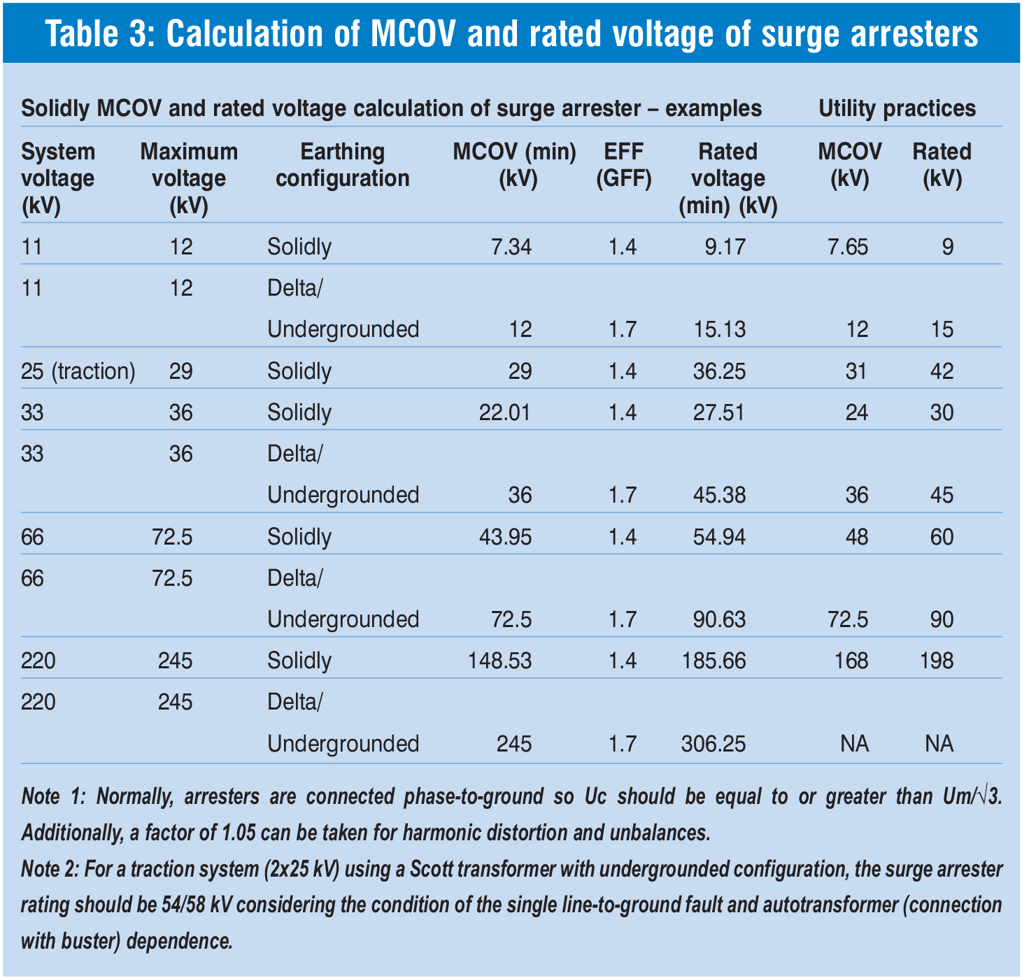
Calculation of maximum continuous operating voltage (MCOV) and rated voltage of surge arresters: The calculations involved in determining the MCOV and rated voltage as well as selected values in utilities are given in Table 3 for reference.
 Conclusion
The system grounding configuration determines the overvoltages that can occur during a ground fault. A single phase-to-ground fault shifts the ground potential at the fault location, depending on the severity of this shift on the grounding configuration. On a solidly grounded system with a good return path to the grounding source, the shift is usually negligible. On an ungrounded system, a full offset may occur and the phase-to-ground voltage on the unfaulted phases approaches the phase-to-phase voltage.
Attempts should not be made to use lower-than-selected rated voltage to improve margins, as this may lead to an unacceptably low temporary overvoltage capability.