 Dr Rajesh Kumar Arora, Senior Manager (Technical), Delhi Transco Limited
Modern society is highly dependent on electrical power supply. To make our lives comfortable, we use a number of appliances/gadgets at home and in the workplace.
However, electrocution, electrical fires and lightning strikes kill 15,000 people a year. In addition, around 75,000 individuals are affected by these tragedies, which also result in a loss of property and assets, shattering the dreams of many people.
The news of electric shocks or electric fires killing people is distressing, and prompts a temporary search for solutions while we wait for the next accident to happen. (refer to Figures 1 and 2)

Figure 1: Electrocution accidents
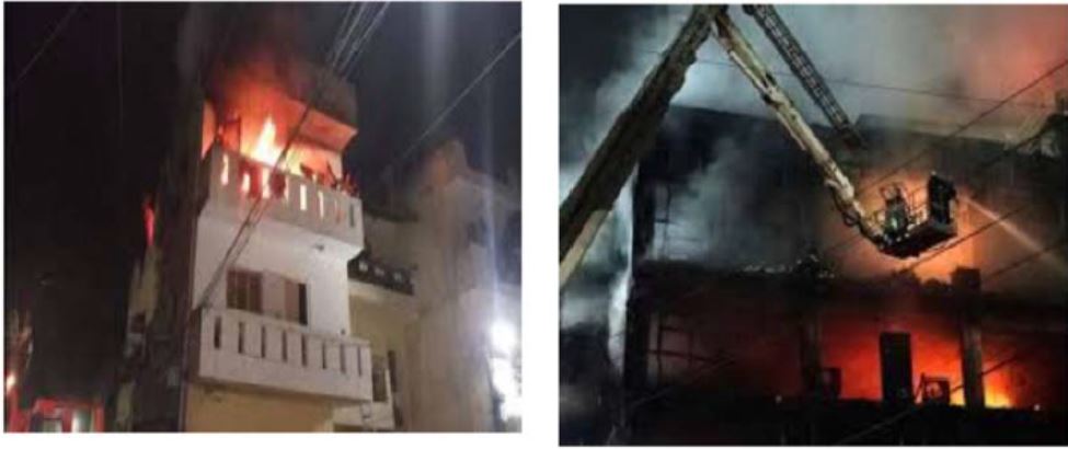
Figure 2: Electrical fire accidents
Every day, there are countless electrical accidents across the country, many of which go unreported or unrecorded.
Keeping the figure for the injured aside, the number of electrocution deaths in the country tell a story of their own. According to the National Crime Records Bureau, around 100,000 people have lost their lives because of electrocution in the past decade. The annual average of fatalities rose to 12,500 per year, that is, 30 fatalities per day. Calling these 30 electrocution deaths per day in India “accidents” is not justified as it insulates stakeholders from accountability.
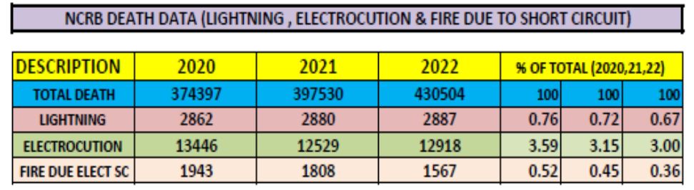
The accompanying table provides detailed data on deaths due to electrocution and fire in the past three.
NCRB data of deaths due to lightning, electrocution and fire due to short circuits (2020-22)
Main causes of electrocution and electrical fire hazards
Electrocution and electrical fires in electrical installations can generally be attributed to the following factors:
- Overcurrents (overloads and short circuits)
- Harmonics
- Earth faults
- Electric arcs in cables and loose connections
- Failure of protection devices or wrong selection of protection devices
- Wrong selection of cables or wires
- Mismatch of illumination fitting ratings and lamps
- Use of extension cords for heaters or any other heavy loads
- Use of outlived (outdated) or damaged equipment
- Over voltages (lightning) and arcing ground
- Consumers have become prosumers
- Inadequate design for earthing/grounding
- Improper or no verification and testing (commissioning or periodical)
Basics of overcurrent in electrical systems
Electrical systems are designed to safely handle currents within specified limits. However, various conditions can lead to overcurrent situations, each with distinct causes, effects and protective measures. This discussion will delve into overcurrent, overload, short-circuit and earth fault currents, providing a comprehensive understanding of their characteristics and implications in electrical engineering.
Overcurrent: Overcurrent refers to any current in an electrical circuit that exceeds the rated or intended value. The causes of overcurrent are:
- Normal operational conditions: Temporary increases in current due to changes in load.
- Abnormal conditions: Faults such as short circuits or ground faults.
- Component failure: Malfunctioning equipment or aging components.
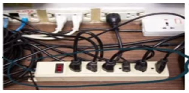 Figure 3: Overloading of the extension board
Overload: It occurs when the current in a circuit exceeds the rated load current for an extended period.
- Causes: Excessive connected load, sustained high-demand periods and inadequate circuit capacity. (refer to Figure 3)
- Effects: Overheating of conductors, insulation degradation and potential damage to equipment.
- Protection: Circuit breakers, fuses and thermal overload relays designed to trip at predetermined overload thresholds.
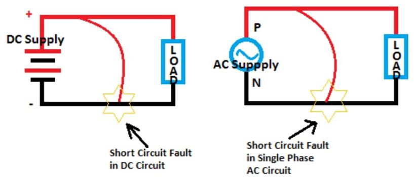 Figure 4: Short circuit in electrical systems
Short circuit: A direct low-resistance path between conductors of different phases or between a phase and ground.
- Causes: Insulation failure, accidental contact between conductors, or equipment faults. (refer to Figure 4)
- Effects: Rapid rise in current, magnetic forces, and potential mechanical damage to conductors and equipment.
- Protection: High-current rated fuses, circuit breakers with instantaneous trip settings, and protective relays designed to detect short circuits.
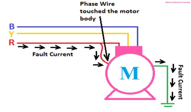 Figure 5: Example of an earth (ground) fault
Earth fault: It occurs when a live conductor unintentionally comes in contact with the earth or a conductive part connected to the earth.
- Causes: Insulation breakdown, equipment faults, or accidental contact with grounded surfaces. (refer to Figure 5)
- Effects: Current flows from the phase conductor to the ground, potentially causing equipment damage and safety hazards.
- Protection: Differential relays, residual current devices (RCDs) and ground fault detectors designed to detect small leakage currents indicative of earth faults.
Characteristics and Implications
- Overload: Typically exceeds nominal operating current by 110-150 per cent.
- Short circuit: Can be several times higher than the normal operating current, limited only by system impedance.
- Earth faults: Generally lower in magnitude compared to short-circuit currents, but significant enough to cause damage if not promptly detected and isolated.
Short circuits in electrical systems
Electrical fires often take place in the residential sector. This is because most people do not account for the rating of appliances while connecting them. Most individuals are not aware about the parameters that must be considered while purchasing a product. The majority looks for cost effectiveness. This may lead to extreme situations such as electrical fires. A key reason for electrical fires in LV systems is short circuits, that is, the flow of current through an unintended path.
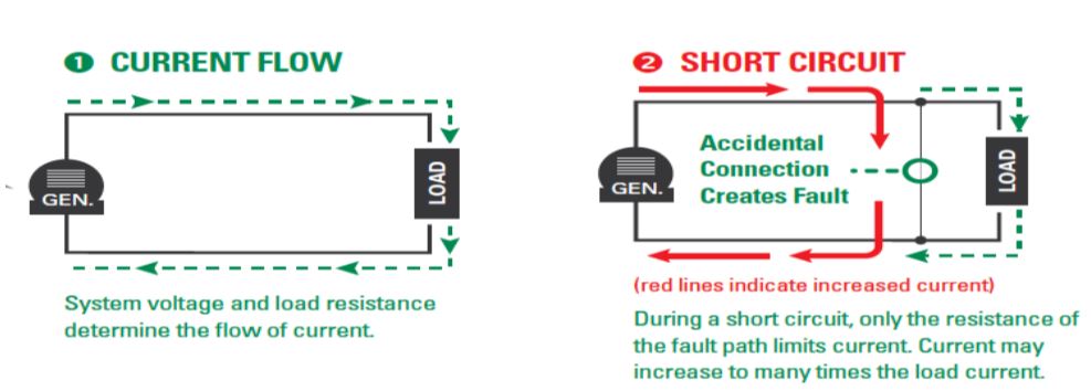 Figure 6: Concept of short circuit
A short circuit is an abnormal connection between two nodes of an electric circuit intended to be at different voltages. This results in an electric current limited only by the equivalent resistance of the rest of the network, which can cause circuit damage, overheating, fire or explosion (refer to Figure 6). This high current generates high heat and the presence of fuel or any other flammable materials can lead to fire hazards as explained by the fire triangle in Figure 7.
 Figure 7: Fire triangle
Short circuit happens mainly due to the degradation of insulation. As wires get old, their insulation degrades, increasing the chances of short circuits (Figure 8) and fires.
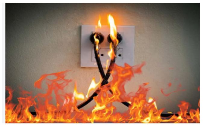 Figure 8: Fire due to insulation failure
Overvoltage in electrical systems
Understanding the internal and external causes of overvoltage in power systems is essential for implementing effective protection and mitigation strategies. Internal factors like switching operations, capacitor switching, faults and resonance require careful design and use of protective devices to minimise transient overvoltages.
External influences such as lightning strikes, electromagnetic interference and grid switching necessitate robust grounding, surge protection and system resilience measures. By addressing these causes comprehensively, power systems can maintain reliability, protect equipment and ensure safe operation in diverse operational conditions. (refer to Figure 9)
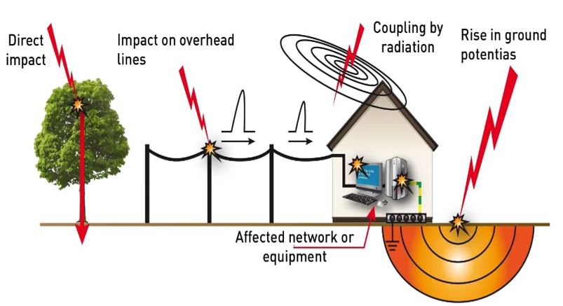 Figure 9: Lightning and its impact on building
Role of adequate earthing/grounding
Grounding/earthing means making a connection to the general mass of earth. The use of grounding is so widespread in an electric system that at practically every point in the system, from generators to consumer equipment, earth connections are made.
There are two types of grounding (refer to Figure 11):
- Neutral grounding
- General (equipment) grounding
 Figure 11: Equipment and neutral earthing
The objectives of general grounding include:
- Providing a low resistance return path for fault currents. This protects both working staff and equipment on the premises (refer to Figure 12).
- Preventing dangerous ground potential rise with respect to remote ground during fault conditions.
- Providing a low resistance path for power system transients such as lightning and over voltages in the system.
- Ensuring uniform potential bonding of conductive objects within a substation to the grounding system to avoid any dangerous potential differences between objects and the ground.
- Preventing build-up of electrostatic charge and discharge within the substation, which could results in sparks.
- Allowing adequate current flow for the proper and safe operation of the protection system.
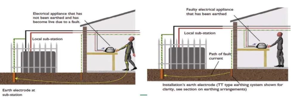 Figure 12: Unearth system and shock hazard
The main objective of grounding electrical systems is to provide a suitably low resistance path for the discharge of fault currents, which ultimately provides safety to working personnel and costly equipment by providing adequate current to safety devices.
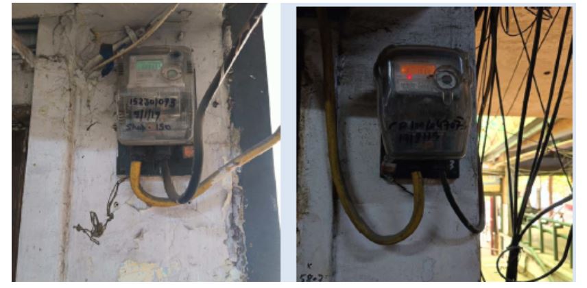 Figure 13: Provision of earth terminals in meter boxes
In India, the use of earthing terminals in switchboards is often inconsistent, and this has serious safety implications. Earthing, or grounding, is a crucial electrical safety measure designed to prevent electric shocks and fires by directing stray currents safely into the ground. Despite its importance, many people in India neglect or fail to implement proper earthing in their electrical systems. (refer to Figure 13)
Understanding the reasons behind this and the associated dangers can shed light on why this issue is so critical. These include:
- Lack of awareness and understanding
- Inadequate implementation and enforcement of standards
- Economic constraints
- Unqualified or undertrained electricians
Dangers associated with the lack of earthing: The dangers of neglecting earthing are severe and multifaceted. Without proper earthing, electrical faults such as short circuits or insulation failures can lead to electric shocks, which can cause injury or even death. Electrical appliances and wiring can become live with stray currents, posing a constant risk to anyone in contact with them. Additionally, the absence of earthing increases the risk of electrical fires, which can result in property damage, loss of life and financial losses.
Basic concept of smart meters
A smart meter is an AC static watt-hour meter equipped with time-of-use registers, internal connect and disconnect switches with two-way communication capabilities. It is designed to measure the flow of forward (import) or both forward and reverse (export) energy, store the data and communicate it along with other parameters defined in the standard. It can be remotely accessed for collecting data/events and programmed for select parameters.
The smart meter is a component of advanced metering infrastructure. For the purpose of this standard, a smart meter is conceived as a single unit comprising the following functional zones:
- Metering
- Load switch
- Metering protocol
- Communication modules
Smart meters have diverse applications, allowing buyers to choose features tailored to their overall system requirements and site conditions. In order to facilitate such a flexible approach, the smart meter architecture is categorised into two variants. The two variants are diagrammatically represented in Figures 14 and 15. These variants are applicable to both built-in type and pluggable type smart meters.
 Figure 14: Variant 1 of smart meters
 Figure 15: Variant 2 of smart meters
NAN: Neighbourhood area network; DCU: Data concentrator unit: HES: Head end system; IHD: In-home display; HHU: Hand held unit
Functional requirements of smart meters
The smart meter developed as per the standard is required to support the following operational requirements:
Disconnection Mechanism: The smart meter shall support disconnection (all the switches shall operate) under the following conditions:
- Over current (minimum 105 per cent of Imax in any phase for a predefined persistence time)
- Load control limit (programmable and set by the utility)
- Pre-programmed event conditions (factory set)
- Disconnect signal from the utility control centre
- In the case of a prepaid facility, under defined/agreed
As per the relevant Indian Standard:
- The persistence time value must be provided by the
- The list of events for pre-programmed disconnection must be provided by the
Reconnection mechanism
The local reconnection shall be as follows:
- The switch reconnection is decided by the meter locally. It will try to reconnect the load up to a predefined time and at predefined intervals (time and intervals are programmable by the utility). If the consumption is within limits, the meter shall remain in normal connect mode
- If the consumption is still more than the programmed limits, it will lock out and wait for 30 minutes (lock-out period). After this period, the meter shall reconnect the load and if the consumption is still above the limit, the procedure as defined above shall be repeated with status updates sent to the HES
- In all conditions other than over current and load control limit, reconnection shall normally be done from the In case of failure of communication with the HES, reconnection is possible through an optical port, adhering to specified security protocols.
- The reconnection mechanism for prepayment meters will align with the agreed prepayment structure with the
Status of load switch: The status of the load switch (connected/disconnected) shall be available on display as well as at the HES.
Load switches for protection against fire and electrocution
Smart meters are sophisticated devices that play a crucial role in modern energy management, offering enhanced capabilities beyond traditional meters. One of their most critical functions is improving safety, particularly preventing fire and electrocution risks. A key component for achieving this is the load switch, an integral feature in many smart meters. This section explores how load switches in smart meters contribute to safety by preventing fire and electrocution, and provides guidelines for their effective use.
Understanding load switches in smart meters
A load switch in a smart meter is essentially a relay or circuit breaker that can control the flow of electricity through the meter. It can be remotely operated and is designed to disconnect the electrical load if certain conditions are met. This capability is crucial for enhancing safety by enabling immediate response to dangerous situations.
Protection against fire
- Overcurrent protection: One of the primary functions of a load switch is to provide overcurrent protection. Excessive current can cause overheating in electrical wiring, potentially leading to fires. Smart meters equipped with load switches can detect when the current exceeds a safe threshold. When this happens, the load switch can automatically disconnect the circuit, preventing overheating and reducing the risk of fire.
- Overvoltage protection: Overvoltage conditions can also pose a fire risk. Smart meters with load switches can protect against this by disconnecting the circuit when voltage levels exceed safe limits. Overvoltage conditions may result from issues such as lightning strikes or power surges. By disconnecting the load, the smart meter helps prevent potential damage and fire hazards associated with these conditions.
Protection against electrocution
Ground fault detection: Ground faults occur when electrical current unintentionally flows to the ground, often through a person or conductive material. This can result in electric shock or electrocution. Smart meters with load switches can incorporate ground fault detection features that monitor for abnormal current paths. If a ground fault is detected, the load switch can quickly disconnect the circuit, significantly reducing the risk of electrocution.
- Detection mechanisms: The load switch in a smart meter can be equipped with ground fault sensors that measure the difference in current between live and neutral wires. Any imbalance, indicating a potential ground fault, triggers the switch to disconnect the load, protecting individuals from electric shock.
- Residual current protection: Residual current devices (RCDs) are crucial for protecting against electrocution. Some smart meters integrate RCD functionality into their load switches. These devices detect residual currents that may indicate leakage or faults in the system. When an unsafe residual current is detected, the load switch disconnects the circuit, thus preventing electric shock.
- Sensitivity settings: Load switches with RCD capabilities can be adjusted for sensitivity, ensuring they react appropriately to varying levels of residual current. Proper calibration is essential to balance sensitivity and minimise false tripping while still providing effective protection.
Health of earthing (grounding) connections
How it works:
- Monitoring voltage levels: Smart meters can measure the voltage between different points in the electrical system, including between live and earth. If there is an open earth connection, the voltage between the live wire and the earth might be significantly different from normal values.
- Detection of abnormalities: Significant deviations in voltage readings can indicate a problem with the earthing system.
Practical guidelines for effective use
To maximise the benefits of load switches in smart meters and protect against fire and electrocution, users and installers should adhere to some practical guidelines:
- Proper installation: Proper installation is critical for the effective operation of safety features. Faulty installation can lead to malfunctions and reduce the effectiveness of protection mechanisms.
- Regular maintenance: Regular maintenance checks on the smart meter and its load switch are essential. This includes verifying that the load switch operates correctly, inspecting for signs of wear or damage, and ensuring that safety features are functional.
- Configuration and calibration: Proper configuration and calibration of load switch settings according to the specific requirements of the electrical system includes setting appropriate thresholds for overcurrent and overvoltage protection and calibrating RCD sensitivity.
- User education: This includes educating users about the importance of load switches and safety features in smart meters, how to recognise signs of electrical problems and what actions to take in case of a safety alert. It can enhance overall safety.
- Emergency procedures: Clear emergency procedures should be established to address faults or safety alerts. Users should be aware of how to safely disconnect the power supply and seek professional assistance when needed.
Conclusion
Overcurrent refers to any current in an electrical circuit that exceeds the rated or intended value. The main causes of overcurrent include momentary increases in current due to load changes, faults such as short circuits or ground faults and malfunctioning equipment or aging components. Overcurrent typically exceeds nominal operating current by 110-150 per cent. Short-circuits can result in currents several times higher than normal operating currents, limited only by system impedance. Earth fault current are generally lower in magnitude than short-circuit currents, but are still significant enough to cause damage if not promptly detected and isolated.
Understanding the internal and external causes of overvoltage in power systems is essential for effective protection and mitigation. Internal factors like switching operations, capacitor switching, faults and resonance require careful design and use of protective devices to minimise transient overvoltage.
In India, the use of earthing terminals in switchboards is often inconsistent, and this has serious safety implications. Earthing, or grounding, is a crucial electrical safety measure designed to prevent electric shocks and fires by directing stray currents safely into the ground. Despite its importance, many people in India neglect or fail to implement proper earthing in their electrical systems.
Load switches in smart meters play a pivotal role in enhancing electrical safety by providing critical protection against fire and electrocution. Through features such as overcurrent protection, overvoltage protection, ground fault detection and residual current protection, these devices help prevent hazardous situations that could lead to severe harm. Proper installation, regular maintenance, accurate configuration and user education are essential for the effective use of load switches. By adhering to these best practices, smart meters can maximise their role in safeguarding against electrical hazards, contributing to a safer and more reliable electrical environment.