
Thermal power generation is a water-intensive industry and thermal power plants (TPPs) in India are some of the largest consumers of water in the world. To optimise the use of water resources in these plants, developers are putting in place complete water management plans. These will help maximise the efficiency of water usage, minimise wastewater discharge to achieve zero liquid discharge, reduce water consumption and encourage a policy of sustainability, water conservation and environmental awareness.
Power Line presents some case studies of significant players in the industry that have taken measures to manage water resources at their power plants…
JSW Energy – Toranagallu power stations
JSW Energy’s operational 860 MW Toranagallu project in Karnataka uses water from the Tungabhadra dam, which is at a distance of 40 km from the plant site, and the Almatti dam, which is at 180 km. The pretreatment of water is undertaken by JSW Steel. The average specific water usage at the project is 2 cubic metres per MWh, one of the lowest in the industry. The plant consumes around 41,000 m³ per day of clarified water.
The water management strategy implemented at the plant covers design, operation and sewage water treatment.
Some of the key systems adopted at the design stage are dry fly ash handling type systems (as opposed to conventional lean slurry systems), efficient drift eliminators in cooling towers and side stream filters installed in circulating water (CW) systems. Further, chemical water treatment methods have been designed to minimise the corrosion and scaling potential of water.
At the plant operation stage, the cycle of concentration (COC) in the CW system has been optimised. The COC is in the range of 6 to 10 for the project. Boiler blowdown is conducted on a need basis (weekly for two hours). JSW also reuses the blowdown water from cooling towers in its green belt and plantation. Further, 100 per cent of the fly ash is used by cement plants, which reduces the power plant’s water requirement for fly ash conditioning. JSW has also implemented a five-year rolling plan to ensure full availability and maximum utilisation of its reverse osmosis (RO) plant. The company has spent Rs 225 million, including capital and operational expenditure, on its RO plant and reed bed system.

The cooling tower blowdown is also used for the fire water system make-up. The treated effluent water is used for meeting seal trough make-up, bottom ash conditioning and in-house requirements. Further, reuse of the demineralisation plant filter water and ultrafiltration backwash water in the cooling tower basin conserves around 200 cubic metres of backwash per day. Seepage water is used for direct contact cooler make-up, while rainwater and water from condenser pits is used for harvesting, and then used in the cooling tower.
While JSW has been making consistent efforts to maintain its water footprint, it is also facing a few challenges. Since 2012, the make-up of water hardness and chlorides has been on a steady rise, thus deteriorating the quantity and quality of the water that the company has access to. The increase in operating costs is another impediment to water conservation efforts.
APGENCO – Sri Damodaram Sanjeevaiah thermal power station
Andhra Pradesh Power Generation Corporation Limited (APGENCO) has a total installed capacity of around 4,560 MW, of which 2,810 MW comes from its TPPs. Its 2×800 MW Sri Damodaram Sanjeevaiah thermal power station (TPS) lies on the coast. The water requirements of coastal power plants can be met from seawater, which presents unique advantages and disadvantages. Coastal power plants have access to plenty of seawater and face limited land constraints. Coal can be transported to these locations by sea or rail. However, they face continuous damage to pipelines due to high total dissolved solids in the seawater, accumulation of salts on switchyard equipment and leakages in ash pond bunds entering the fertile land in the area.
The water required by the project for condenser cooling is 100,000 cubic metres per hour, per unit. Together the units consume 13,800 cubic metres of seawater per hour, totalling 331,200 tonnes of seawater intake per day.
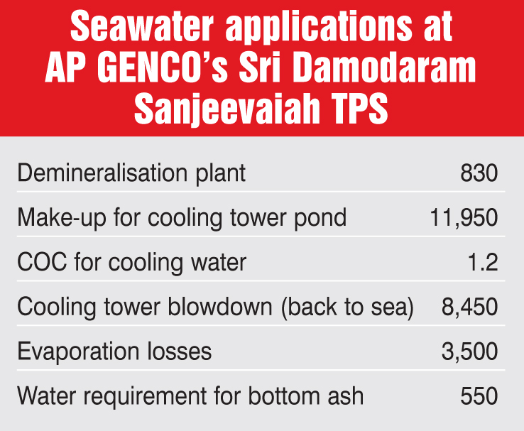
The seawater must be treated before it is used in the TPP. For this, APGENCO has an RO plant where the seawater first goes through a clarifier, and then gets filtered through demineralisation or active carbon filters before undergoing the first RO cycle. From the first RO unit, the treated seawater is either rejected back into the sea, used as service water or sent further to the second RO unit. After passing through two stages of RO, it is treated using a mixed bed system, for further purification, after which it is stored in a dual medium storage tank.
Considering the fixed availability of water resources while the water requirements keep increasing, APGENCO has put in place a plan to optimise its water usage. Thus, the company uses a Rankine cycle dry cooling system for condenser cooling. A wet cooling system is used only for auxiliary cooling water. Meanwhile, bottom ash disposal is undertaken through dry mode. Further, outlet water from effluent and sewage treatment plants is recycled and used for gardening and cleaning.
While the dry cooling system minimises the water requirement and the environmental impact, it reduces the plant output by 7 per cent and increases the heat rate by 7 per cent. Further, the thermal efficiency of the plant decreases from 38 per cent to 35 per cent, and coal consumption increases by 7 per cent. These factors amount to an increase in the plant cost by 10-14 per cent.
APGENCO’s plans to further reduce water consumption and achieve zero discharge include treating blowdown and RO discard water at an RO treatment plant and reusing the same as cooling tower make-up. Water from boiler auxiliaries will also be recycled and high water loss in ash handling will be brought down by recycling overflows.
CESC Limited – Budge Budge Thermal Power Station
In 2015-16, the 750 MW Budge Budge Thermal Power Station (TPS) recorded a specific water consumption of only 2.25 cubic metres per MWh. Since 2010-11, the plant’s water consumption has been impressive and in the range of 2-2.3 cubic metres per MWh.
Water for the Budge Budge power plant is sourced by CESC from the Hooghly river, and the average daily intake is approximately 40,000 cubic metres. About 8,000 cubic metres of water is recycled daily from the holding pond. Water from the river and the holding pond is passed through a raw water treatment plant before being separated into clarified water and demineralised water.
To conserve water used in the cooling towers, a closed circuit cooling water system has been put in place. Further, the company is making attempts to establish a zero effluent discharge station, in which effluents from the pump house and canteen will be reintroduced into the holding pond rather than being dumped into the municipal drainage. This water is then treated and reused. Further, water from the condenser, which was earlier discharged into the Hooghly, is being used for station services, after which it reaches the holding pond. The activated carbon filter backwash effluent is also diverted into the holding pond for recycling.
Treated wastewater from the neutralised demineralisation plant is stored in a fish pond conducive to pisciculture, further minimising wastage. The bottom ash management system is also a zero discharge system. Further, rainwater is harvested and used as cooling tower make-up.
CESC has switched to an all-volatile treatment method, in which ammonia and hydrazine are used, thus eliminating the need for phosphates in the boiler system. This has led to zero blowdown from boilers, savings in demineralised water and boiler feed pump water, reduced wastage of chemicals, and improved plant efficiency. This also avoids carrying of solid chemicals to superheaters and the phosphate hideout, which can be seen in conventional congruent phosphate control systems.
Some of the measures taken to improve the specific water consumption at the Budge Budge TPS are increasing the COC of the cooling tower circulating water system by dosing corrosion inhibitors or anti-scalant special chemicals and monitoring the calcium hardness level, resulting in reduced cooling tower blowdown. The COC has been increased from the range of two to three cycles to five to six cycles.
Water consumption has been further reduced by changing the mode of operation of the inclined-surface settler hopper blowdown from continuous to intermittent. There has also been a drastic reduction in water usage due to better coal pile management through thermography, segregation and compaction. CESC uses dry fog instead of conventional water spraying to control fugitive emissions in dust-prone areas.
Despite these measures to curtail water wastage, CESC faces challenges in sustaining its performance, which entails exploring new avenues while adhering to Ministry of Environment, Forest and Climate Change (MoEFCC) norms. The rising river water salinity also poses challenges.
Damodar Valley Corporation
The total capacity of the Damodar Valley Corporation’s (DVC) power stations is 7,557.2 MW. It was formed in 1948 as the first multi-purpose river valley project in India, and thus has extensive experience in managing water resources in its command area. It sources its water through a network of four dams on the Barakar, Damodar and Konar rivers.
Some of the steps DVC has taken for water management at its TPPs are collection of adequate data to model the plant water and wastewater streams efficiently, and formation of a central water management team to provide guidelines and monitor the best water management practices.

In line with the Central Electricity Authority’s guidelines, DVC’s Durgapur Steel TPS and Koderma power plant, with a capacity of 2×500 MW each, have been designed considering the water consumption requirements under balanced conditions with a total consumption of 3,375 cubic metres per hour.
The focus areas for the optimisation of water consumption are cooling water system make-up, the ash handling plant (AHP) system, power cycle make-up, the potable water system, the service water system, the coal handling plant area and plant surface drains.
A typical 500 MW coal-fired unit requires 60,000 cubic metres of cooling water per hour for condenser and auxiliary cooling with temperature rise of about 10.3 °C across the condenser. DVC has optimised its cooling water system by using a closed cycle system. In this system, make-up water is added to the cooling water system to compensate for water losses on account of evaporation, drift and blowdown to maintain the desired level of dissolved solids in the circulating water. Further, the blowdown water is used to dispose of bottom ash, and the unutilised blowdown is led to the central monitoring basin (CMB) of the plant for further utilisation, treatment and disposal outside the plant boundary. The quantum of blowdown water is further reduced by increasing the COC of the cooling water system from 4 to 6. Chemical dosing for cool water treatment involves the introduction of anti-scalants or corrosion inhibitors. DVC has also introduced side stream filters to arrest the total suspended solids in cooling water basins.
High density polyethylene lining has been installed in raw water reservoirs to prevent loss through leaching and seepage. Also, the wet ash disposal method has been adopted with a slurry concentration of 30 per cent for fly ash and 25 per cent for bottom ash. Meanwhile, 70-80 per cent of ash pond water is recovered and reused in AHPs, resulting in a net reduction of 20 per cent in the water supplied for ash disposal. Further, water requirements for ash disposal are reduced by reusing water from cooling tower blowdown, the central monitoring basin and the ash washing recirculating system.
DVC has installed polymer lining in its ash ponds to prevent the leaching effect on the groundwater and the seepage loss. Further, dry fly ash evacuation of around 2.2 million tonnes in 2015-16 from DVC plants has resulted in a significant reduction of ash water make-up. DVC also maintains the cleanliness of clarifiers, aerator trays, launders, etc. by preventing the growth of organics in the pre-chlorination system and improving coagulant dosing for clarification. Demineralisation plants older than 10 years have their exchanger resins fully replaced, significantly improving the quality of demineralised water and reducing the make-up percentage. Ultrafiltration systems have been installed in all demineralisation plants, reducing the problem of colloidal silica in boiler water, thus minimising boiler blowdown to a great extent. Also, reduction in the start-up time of 500 MW sets by three hours has resulted in additional savings of demineralised water.
At DVC plants, the coal handling plant dust suppression system works in an almost closed cycle with lower make-up by recovering water from drains of coal yards in coal slurry settling ponds and reusing it for coal dust suppression water systems.
The plant drains and side stream filter backwash are treated in effluent treatment plants, and the recovered water is collected in the CMB. The water requirement for low-grade applications such as coal dust suppression, ash water make-up and gardening is met from the CMB. The consumption of potable water and service water has also been reduced to a great extent (3-5 per cent) in a very simple and traditional way by periodic checking and rectification of float valves in different overhead tanks.
With the combined steps taken towards reduction in water consumption in several areas, DVC has been able to run its plants at a specific water consumption of around 3 cubic metres per MWh.
Conclusion
Operators of Indian power plants are using the best technologies available to minimise the wastage of water, improve the efficiency of their systems to comply with the water usage norms established by the MoEFCC and remain profitable. These measures will only continue to grow in significance going forward. n
With inputs from presentations by DVC, CESC Limited, JSW Energy and APGENCO at a Power Line conference


