Lightning is an atmospheric discharge and one of the major causes of power system outages. This issue crops up frequently, accounting for as much as 40 per cent of the total outages experienced. Such outages translate into a significant loss in revenue and lead to many unsatisfied customers. Thus, consumers are demanding fewer interruptions and improved reliability.
The effects of lightning are wide and vary with the current, which ranges from 2 kA (85-90 per cent) up to 200 kA (probability 0.7-1.0 per cent). Thus, if the power equipment is not protected, over-voltage may lead to burning of insulation resulting in the complete shutdown of the power system and subsequently the consumer service entrances connected to the power system.
Thus, there is an urgent need to manage the risks pertaining to lightning. To this end, lightning hazard evaluation, which is based on the lightning occurrence frequency, the peak values of lightning currents, and the energy of lightning, needs to be undertaken. Lightning risk assessment can help reduce the risk or damage caused by lightning.
Global standards
In 2006, all the earlier standard documents were substituted by a single multi-parts standard (IEC 62305 – 1 to 4), providing the general principles of protection against lightning, risk management, measures to prevent life hazard and physical damage to structures electrical as well as electrical and electronic systems within structures. The global standards used in lightning protection are as follows:
- IEC 62305-1: It lays down the terms and definitions, lightning parameters, basic criteria for protection and test parameters to simulate the effect of lightning on lightning protection system components. It also highlights the damages caused by lightning.
- IEC 62305-2: “Protection against lightning” provides the risk assessment method and its evaluation. It requires a risk assessment to be carried out to determine the characteristics of a lightning protection system before installation. In order to perform the risk management proposed in IEC 62305-2, 2006, the cloud-to-ground lightning frequency per kilometre square and per year is needed. This parameter could be achieved with a network of appropriate sensors connected to a computer, which validates and records data events.
- IEC 62305-3: It is focused on protection measures to reduce the physical damages and injuries of living beings due to touch and step voltages.
- IEC 62305-4: It considers the protection of electrical and electronic systems against lightning electromagnetic pulse within the structures.
- IEC 61400-24: It focuses on the application of existing standards to wind turbines in order to provide effective lightning protection to the entire system. It recommends that wind turbines should be modelled as a tall mast with a height that is equal to the hub height and one rotor radius.
Technology overview
Lightning protection systems could be external or internal. External protection systems are installed to prevent direct lightning strikes from penetrating roofs or structures, and causing a fire due to intense heating.
The external protection system consists of collectors (air terminals) to intercept lightning strokes, conductors to conduct surge currents to the ground, and an earth interface to dissipate the surges to earth. These collector/diverter systems encourage the termination of lightning bolts in “protected” areas by providing termination points. However, these are deployed in such a manner that they actually increase the risk of a strike in that area.
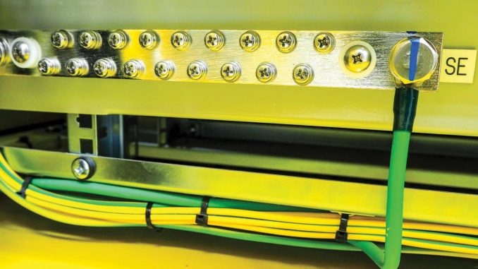
The external protection system has three parts – an air termination system, a down conductor and an earth termination system. The down conductor is used to provide the low impedance path from the air termination system to the earth system. Any good conductor, which forms a part of the building structure, can be employed as a down conductor with appropriate connection to the air termination and earthing systems. Down conductors can be isolated or non-isolated.
Non-isolated systems are not considered ideal for the protection of technology on the roofs of buildings. In this case, the rooftop equipment, metallic items and the structure itself may also carry a proportion of the discharge current. This can be potentially devastating in the current building environment, which comprises rooftop telecommunication masts, air-conditioning units containing sensitive electronic equipment, etc. These may be subjected to partial lightning discharge currents. Thus, a very rigorous bonding procedure must be followed, with no exceptions.
Isolated systems, which are less common, also use a network of air terminals, down conductors and grounding electrodes. However, isolated systems have a multilayered insulation and a semi-conductive outer sheath. This makes them resistant to upper terminations down to the first grounded bonding point, thus eliminating partial discharges. Partial discharges of bare conductors may form on the cable surface during immediate voltages, which may cause thermalisation or a breakdown. Typically, this arrangement requires a special layered termination fitting made of metallic, stress-relieving and anti-tracking components.
In this system, the lightning current carrying conductor is wrapped with insulating material in such a way that the required separation distance from other conductive parts of the building, electric lines and pipes is maintained. The coaxial conductor consists of an inner copper conductor with a high-voltage-resistant thick-walled insulation and a weather-resistant semi-conductive special outer sheath. Thus, a creeping flashover along the surface of the conductor is prevented. Thus, isolated down conductors are an ideal solution for external lightning protection systems on residential and industrial buildings, wind turbines, photovoltaic (PV) systems, biogas plants, mobile phone antennas and systems of the process industry.
Surge arresters
Internal system protection systems are installed in the case of indirect lightning, which strikes close to an object. Short-time voltage impulses resulting from a strike spread along supply lines. These can access various electrical lines in the object through electromagnetic induction. These additional voltage peaks of several thousand volts can damage connected devices such as televisions, satellite receivers, computers, house appliances, alarm and monitoring systems and PV systems. Even phone lines and computer networks could be affected. Therefore, the protection of electrical equipment against this kind of electromagnetic coupling is done with surge arresters. Surge arresters are protection devices with a very high resistance to threshold voltages. Once a surge voltage appears, the resistance of these arresters reduces, thus abruptly reducing the surge voltage. Surge arresters show a very small time delay during a lightning stroke.
The surge arresters used for the protection of exterior electrical distribution lines include metal-oxide surge arresters (MOSA), with resistors made of zinc oxide (ZnO) blocks, or gapped type with resistors made of silicon-carbide (SiC). Expulsion-type units are no longer used. Metal-oxide (MO) surge arresters are widely used as protective devices against switching and lightning overvoltages in power systems. The distinctive features of MO arresters are extremely non-linear voltage current, ignorable power losses, high-level reliability in the operation time, high speed response to overvoltages, simplicity of design, easy maintenance and long life. Accurate modelling and simulation of their dynamic characteristics is very important for arrester allocation, systems reliability and insulation coordination studies.
The gapped-type arrestors with resistors made of SiC include infusible refractory materials of limited conductivity and comparatively low specific resistance in the silicon carbide family. The properties greatly enhance the effectiveness, durability, stability and simplicity of surge arresters.
Advancements in surge arrester monitoring are also possible. This could result in a whole new generation of devices that are more accurate, reliable and power efficient while also being multifunctional and intelligent.
Currently, the most frequently used technique is the arrester leakage current to assess the condition of an arrester and evaluate its leakage current. This consists of a dominant capacitive component and a small but essential resistive component. Any change in the current and voltage characteristic of an MO arrester brings about a negligible change in the capacitive amount, but a significant change in the resistive amount of the leakage current. Further, there is a technique for recording impulse currents, which that evaluates the condition of an arrester, the number of discharge incidents and amplitude measurements of the discharge current.
When recording impulse and leakage currents over a long period of time, the monitoring device has to be installed on the arrester earth. A standard smartphone with near field communication (NFC) function is used as the main device for data transmission. NFC is a radio standard that is energy efficient and can transmit data over a few centimetres.
Conclusion
Lightning protection technologies for power systems have been in use for more than 100 years, and new ways to mitigate the effects of lightning are being introduced every year. For the successful implementation of these technologies, greater investments and awareness are needed.


