Although generation resources are concentrated in a few places in India, the transmission system network is spread over the entire length and breadth of the country. To cater to the increasing demand of such a large country, the transmission network needs to be strengthened, utilising minimum right of way (RoW). In the past decade, transmission networks have grown exponentially. Transmission lines through the tariff-based competitive bidding route have increased, which has attracted greater awareness on RoW. A transmission line may pass through different land use areas such as densely populated areas, agricultural areas, forest areas or hilly or mountainous areas. The width of RoW becomes critical in densely populated areas because of non-availability of land required for the conventional width of RoW. Some other issues include high cost of land, difficult terrain and forest areas where conservation of flora and fauna is crucial.
The various strategies to conserve RoW include bulk power high capacity lines, uprating of existing lines, and focusing on alternate line and tower configurations. Thus, a robust tower foundation becomes indispensable for a reliable transmission network. New tower foundation designs seek to customise structures to suit the local terrain and reduce the time required for construction.
Key considerations for tower foundations
Transmission line foundations can have significant environmental impact as such structures entail huge consumption of construction material, energy and water. They also generate a lot of dust, adding to air pollution. Developments are under way in foundations to reduce environmental impact and deploy strategies to minimise it by proper use of natural resources, improved energy efficiency, avoiding pollution, and protecting and enhancing biodiversity.
Proper use of natural resources can be achieved by using lean designs (the best method that requires minimum resources), designs that avoid pollution, use of recycled/sustainability sourced products like crusher dust and water management techniques. Pollution can be avoided by minimising emissions; preventing nuisance from noise and dust through good site and depot management practices; minimising and eliminating waste; and preventing pollution incidents and breaches of environmental norms. In addition, protection of sensitive ecosystems can be achieved through good construction practices and supervision. Further, alternate line/ tower configurations can be deployed to conserve RoW such as double-circuit/ multicircuit transmission lines, and compact structures like delta-type and tall structures.
Foundation design types
A lean design minimises the use of construction material, thereby leading to saving of energy and transportation costs. Innovation in foundation shapes is taking place and new types of foundations have been introduced. Introduction of intermediate angle foundation and innovation in design techniques such as curtailment and stub as reinforcement have also gained traction in recent times. Environment-friendly designs include precast foundation, grillage foundation and auger foundation.
Precast foundation is preferred where the time of construction is limited. Dimensions of these foundations are governed by the uplift capacity of cranes. Precast foundations offer a number of advantages. Since they are manufactured in factories in a controlled casting environment, it is much easier to control the mix, placement and curing, thus allowing for easier and more stringent quality control. Fluctuations in weather do not affect the implementation of the project. Also, less labour is required on site when using precast foundations, and that labour can be less skilled. Once on site, the precast foundation can be installed immediately and no waiting time is required for it to gain strength. The modularity of precast foundations makes the installation quick. Accelerated curing, by heating precast parts, greatly improves the strength, reducing the time between casting the part and putting it into service. Primarily, such a tightly controlled process, from materials to consolidation to curing, creates extremely durable concrete foundations.
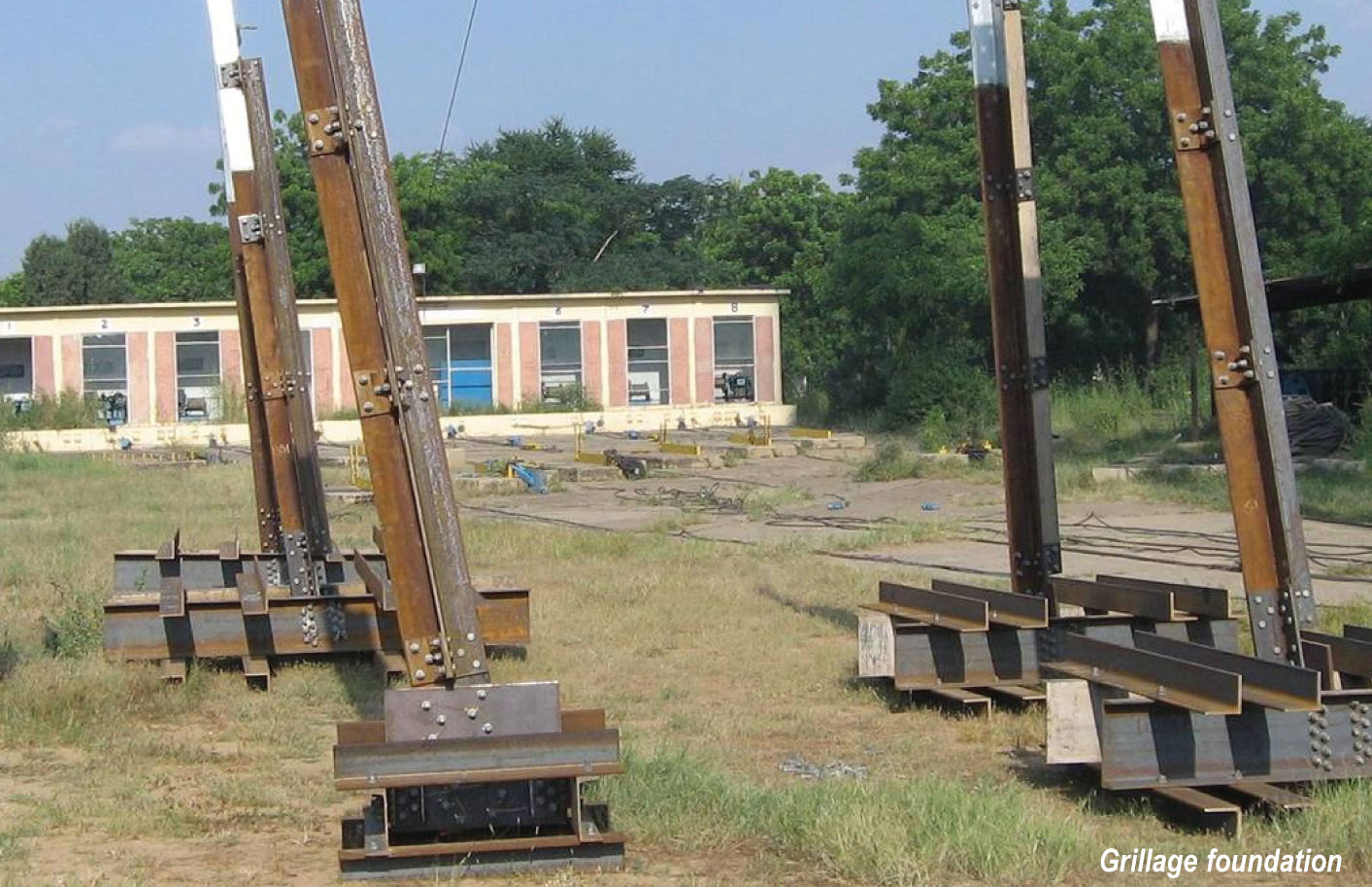
 Grillage foundation is used in a firm soil,where concreting is costly. They usually do not need a concrete pour, so concrete-related transporting and curing time is not required. Further, it is a factory-made foundation. Thus, grillage foundations require minimal installation time and allow immediate tower assembly. It is relatively lighter and consists of a number of layers of beams, usually laid at right angles to each other and used to disperse heavy point loads from the superstructure to an acceptable ground-bearing pressure. The grillage beam can be of any material, usually steel, precast concrete or timber. Common grillage foundation configurations that connect the tower leg to the grillage plate include pyramid supports, a single tubular member and a single leg stub. However, a major drawback of a grillage foundation is the necessity of relatively deep excavation for its installation. Sometimes, due to variations in soil environments along the power line route, tower foundations need to be enlarged by pouring a concrete base around the grillage if the actual soil conditions are not as good as those assumed in the original design. Also, large grillages can be difficult to set up and require accurate adjustments for tower installation.
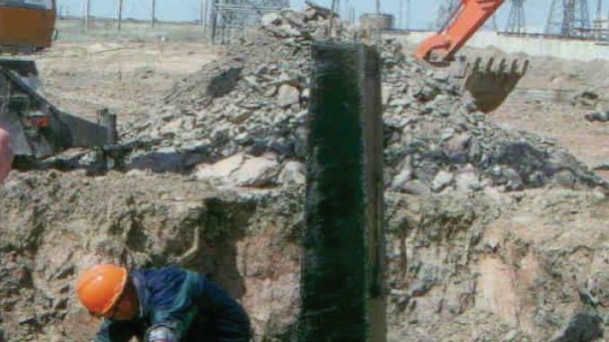
 Auger foundation is another widely deployed type of foundation. Direct embedment foundation is another common type of foundation, which involves the construction of transmission line structures by augering a hole in the ground, placing the base of the pole in the hole, and backfilling the annulus between the pole and the hole. Direct embedment is quite beneficial as it eliminates the need for a costly anchor pole base footing, requires lesser time for installation, and is independent of weather conditions, and does not have any exposed base plates or anchor bolts.
Pile-type foundations may be considered for towers in flood-prone areas based on the soil investigation report and the latest high flood data, notes a recent Central Electricity Authority (CEA) report examining tower failures in the country. Pile foundation is the most common type of deep foundation used to transmit structural loads into deeper layers of the firm soil in such a way that the layers of soil or rock can sustain loads. A pile foundation is generally more expensive than an ordinary shallow foundation, and is used where soil at, or near, the surface is of poor bearing capacity or settlement problems are anticipated. One of the main functions of piles is to carry more load from the superstructure to the lower, more resistant soil strata, thus increasing the load capacity of the site. Generally, piles are made of timber, steel, concrete, or some combination of these materials. Besides the design, proper drainage and protection work/retaining walls should be provided for tower foundations especially in steep slopes/hilly terrain to avoid damage to tower foundations, according to the CEA.
Challenges and the way forward
According to vendors, the competition in transmission line tenders has increased manyfold today. As a result, contractors are submitting quotes with minimum margins and the speed of execution has increased drastically. Clients want to execute the project in the minimum possible time (36-month projects are squeezed to 24 months). Correspondingly, there is a drastic reduction in the design time. Thus, there is a need for increased speed and accuracy of design and detailing. Lack of well-experienced designers and detailers to accomplish the above is one of the major challenges in design. Availability of test beds for testing is another big challenge faced by the industry. This also impacts the project completion time. Further, maximum optimisation of tower weight has become an essential requirement. Intermediate towers, apart from standard (A, B, C and D) are being introduced as a strategy to make up the project cost. Hence, the number of tower designs is increasing and untested towers are not acceptable to customers.
The importance of selecting the most suited foundation for towers increases as the transmission network continues to expand across varied terrain. Increasing loads from lines that carry higher voltages also require bigger and heavier tower foundations. Given these diverse requirements, it is clearly essential to focus on building appropriate and robust tower foundations.
