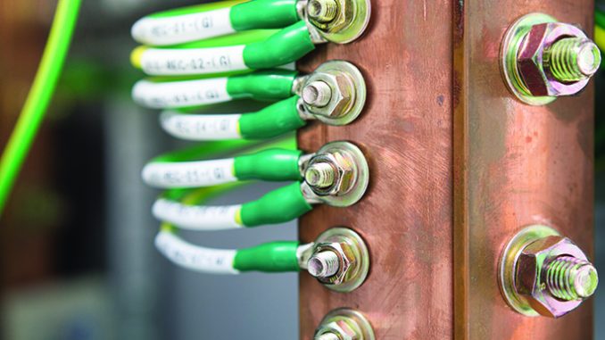
Earthing is an essential element in safeguarding the operations and thus the performance of generation, transmission and distribution systems. The process of transferring the immediate discharge of electrical energy directly to the earth with the help of low resistance wire is known as electrical earthing. A proper earthing system provides the easiest path to the flow of short-circuit current even after insulation failure and protects the apparatus from damage. It also ensures personnel safety from high voltage surges, lightning discharge and short-circuit current.
Overview
The Central Electricity Authority (CEA) defines earthing as the electrical connection between non-energised conducting parts and the general mass of the earth by an earthing device. As part of the earthing arrangement, all the exposed conductive parts must be connected and the system must be capable of discharging the lightning current, avoiding a voltage rise in the earthing system itself and the surrounding ground. The earth electrode must have a low frequency resistance value and all the earthing components must offer low resistance to the earth as well as have excellent corrosion resistance, as they will be buried in the ground for many years. The main components in an earthing system include an earth cable, an earthing joint (earthing lead) and an earth plate.
The International Electrotechnical Commission (IEC) standardised three earthing systems and defined the corresponding installation and protection rules under IEC 60364. These rules define three earthing systems:
- Exposed conductive parts connected to neutral, known as TN
- Earthed neutral, known as TT
- Unearthed (or impedance earthed) neutral, known as IT.
The purpose of all these earthing systems is to protect people and property. Globally, three earthing arrangements are followed that are depicted by two letter codes – TN, TT and IT. While the first letter indicates the connection between the earth and the power supply equipment (generator or transformer), the second letter indicates the connection between earth and the electrical device being supplied on the consumer side. In the TN system of earthing, the source is directly earthed at one or more points. The conductive parts of the installations are connected to the earth through the earth points of the source by a conductor. This allows earth fault currents in the installations to pass through the earth via the earthing point of the source. In the TT system of earthing, the source is earthed but the conductive parts of the installations are connected to the earth through one or more local earth electrodes. The local electrodes do not have any direct connection to the earthing system of the source. The TT system is applicable for both three-phase and single-phase installations whereas the IT system is generally suitable for an unearthed three-phase network. Here, the three-phase source is either isolated or connected to earth through a high impedance of suitable value. The conductive parts including the metal body of the installations are connected to the earth through one or more local earth electrodes.
Types of electrical earthing
An electrical system consists of two non-current carrying parts. These parts are neutral of the system or the frame of the electrical equipment. Earthing can be classified into neutral earthing and equipment earthing based on these two non-current carrying parts of the electrical system. In neutral earthing, the neutral of the system is directly connected to the earth with the help of galvanised iron wire. Neutral earthing is also called system earthing. This type of earthing is mostly provided in a system with star winding. For example, neutral earthing is provided in generators, transformers, motors, etc. Equipment earthing is provided in electrical systems. The non-current carrying part of the system such as the metallic frame is connected to the earth with the help of a conducting wire. If any fault occurs in the system, short-circuit current passes through the earth with the help of the wire, thus protecting the system from damage.
Conclusion
Typically, in the case of generating stations, substations and industrial installations of voltage exceeding 33 kV, the system neutral earthing and the protective frame earthing are integrated into the common earthing grid, provided the resistance to earth of the combined earth mat does not cause the step and touch potential to exceed its permissible limits.
Net, net, in order to protect electricity systems and equipment from damage and minimise risks, it is imperative for utilities to deploy proper earthing systems to ensure continuity in business operations. This calls for the need to have appropriate safety parameters in place as well as regular maintenance of all electrical assets of the network. Following this, testing and measurement procedures will become the prerequisite for respective utilities. On the maintenance front, best practices can be adopted to further protect electricity equipment from overvoltage and thus from damage.
