 By Swapan K. Bhowmick, Advisor, Teestavalley Power Transmission Limited
Insulation coordination is the process of correlating the dielectric strength of electrical equipment and the characteristics of protective devices with expected over-voltages. The entire aspect of insulation coordination is based on the statistical phenomena of probability of overvoltage as well as probability of disruptive discharge of insulation due to overvoltages. The risk of insulation failure depends on the probabilities. Although a certain risk of failure is acceptable, how large a risk can be tolerated depends on economic and service reliability considerations. Therefore, the insulation level relates more to the statistical data than to mathematical function.
Overvoltages causing stress on dielectric strength of insulation may be classified as follows:
- Power frequency (temporary) over-voltages
- Switching impulse overvoltages
- Lightning impulse overvoltages
 Temporary overvoltages are caused by earth faults, sudden load rejection, resonance or ferro-resonance, other system contingencies and are in the form of undamped or slightly damped oscillations, having frequency equal or close to power frequency and persisting for a duration of a few cycles to a few seconds. Switching impulse overvoltages are caused by power line switching, high speed auto-reclosing, out-of-phase switching of cable, capacitor bank, shunt reactor, circuit breaker re-striking persisting for a duration in the range of thousand microseconds. Switching impulse overvoltages are predominant in a power line of 400 kV voltage level and above, due to line charging current and must be controlled to avoid the need for higher insulation. Lightning impulse over-voltages are independent of system voltage, but depend on system impedance and are caused by direct strokes on the conductor persisting for a duration in the range of microseconds.

Further, back flash-overs and lightning strokes to earth very close to a power line can result in induced lightning impulse. The magnitude of back flash-overs would be higher if ground impedance of a tower is high due to presence of rocky soil. During summer thunderstorms, negatively charged direct strokes are most common. Positively charged direct strokes appear more frequently close to the ocean and are very common in winter thunderstorms. Positively charged direct strokes are single shot flashes having greater current magnitude and a very slow front of wave while the negatively charged direct strokes appear with less current magnitude.
 The dielectric strength of equipment is based on its rated insulation level. The external insulation of a power line comprises self-restoring air and solid insulation in the form of insulator strings consisting of disc insulators and long rod insulators. In equipment designed for system voltages below the 400 kV level, the insulation level is determined by the rated lightning impulse withstand level and power frequency voltage withstand level. For a system voltage of 400 kV and above, insulation is determined by the rated switching impulse withstand level and rated lightning impulse withstand level. This is also known as the basic impulse level. Other factors that affect the electrical insulation are altitude and climatic conditions such as pollution and relative humidity. Pollution determines the creepage distance of insulation. The length of the insulator string of a power line is based on the lightning impulse withstand level, switching impulse withstand level, power frequency voltage withstand level and service conditions such as altitude, pollution and humidity.
For economic reasons and industrial practice, equipment is designed to withstand the required withstand voltage within the range of normal service conditions viz. maximum ambient temperature of 40 °C, altitude not exceeding 1,000 metres. Accordingly, standard insulation levels, which 400 kV AC equipment can withstand, for normal service conditions have been adopted as indicated below:
- Lightning impulse withstand level: 1,550 kV
- Switching impulse withstand level: 1,050 kV
- Power frequency withstand level: 680 kV
For altitude exceeding 1,000 metres, necessary atmospheric correction factor is taken into consideration. The dielectric strength of air is influenced by air density (temperature and pressure) and humidity. Such effects need to be taken into account when external insulation is designed and tested. The relative air density and the absolute humidity also have co-effects on the dielectric strength of air. As an approximation, it may be considered that dielectric strength of air is proportional to the relative air density for shorter gaps and the dielectric strength of air is less than proportional to air density for longer gaps. The altitude correction method recommended by IEC 60071-2 is the most suitable for the purpose of insulation coordination and determination of type test voltage. It can be applied to altitude correction for altitudes up to 4,000 m. Altitude correction factor (k) for air insulation should be applied for equipment to correct the altitude (H) exceeding 1,000 m as given in the following formula:
k=em(H-1000)/8150)
Factor “m” is dependent on gap length, gap structure, voltage type and relative air density. For LIWL, m=1 and for SIWL, m=0.75.
For equipment operating at an altitude higher than 1,000 metres, the clearance requirements are increased by 1 per cent for every 100 metres above 1,000 metres.
Altitude correction factor should also be applied for creepage distance, which is based on power frequency voltage and pollution level. Altitude correction for creepage distance is considered the same as for air insulation correction with m=0.5.
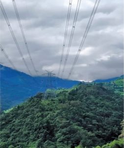
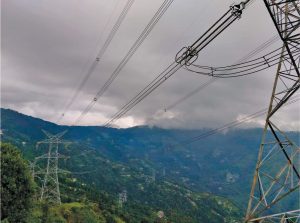
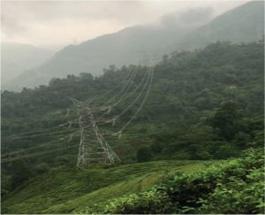
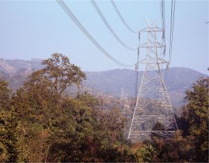 Teestavalley Power Transmission Limited has implemented an interstate 400 kV double circuit quadruple ACSR moose conductor power line of length 215 km for the evacuation of power from a large hydro generating complex in Sikkim of around 3,000 MW in the Teesta river basin. The power will be supplied to the eastern region, for onward transmission to the northern region/western region. The power line emanates from the 400 kV pothead yard of the Teesta III hydroelectric project (HEP) of 1,200 MW capacity located at Mangan in north Sikkim, the second largest HEP in India, and terminates at the 400 kV Kishanganj GIS pooling station in north Bihar. Two 400 kV XLPE cables connect the pothead yard and the 400 kV GIS switchyard of the Teesta III HEP located at altitudes of 870 metres and 792 metres respectively. The dam of the Teesta III HEP on the Teesta river is located at the confluence of the rivers Lachung and Lachen at an altitude of 1,590 m. It is situated at Chungthang near the Indo-China border. The inter-state overhead power line travels in the most difficult hilly terrain of north, east and south Sikkim. More than half of the total 589 towers of the line are located in the steep hill slope with an altitude as high as 2,600 metres where hard rock soil and dry fissured rock are predominant. Due to this tower footing resistance increases to a large extent. All the towers in the hilly terrain consist of chimney extensions up to 12 metres as well as leg extensions of length from (-) 9 metres to (+) 9 metres. Many towers also consist of body extensions up to 30 metres. Rest of the towers are located in the plains of North Bengal and North Bihar at altitudes up to 1,000 metres. The maximum height of a tower from the highly undulated lowest ground level in the steep hilly area including chimney extensions, leg extensions and body extensions, is as high as 117 metres. The entire terrain is highly prone to lightning with isometric level of 50-60 per year.
Lightning surge overvoltage was computed on pothead yard terminals of the Teesta III HEP with direct lightning stroke on the first tower of the 400 kV Teesta III-Kishanganj line with lightning currents of 120 kA corresponding to negative flashes and 200 kA corresponding to positive flashes. The maximum lightning overvoltages at pothead yard terminals with 120 kA negative flashes and 200 kA positive flashes were determined as 1,140 kV and 1,240 kV respectively. These lightning overvoltages were within safety margins of 25-15 per cent, with the lightning impulse withstand level of 1,425 kV, as specified for switchyard equipment.
Based on the basic impulse level of 1,550 kV, the switching impulse withstand level of 1,050 kV and the power frequency withstand level of 680 kV, Teestavalley Power Transmission Limited has selected the following composite long rod insulators on the 400 kV D/C quad moose Teesta III HEP-Kishanganj line in plain terrain with an altitude of up to 1,000 metres:
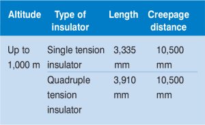
These composite long rod insulators for altitude up to 1,000 m were type tested for the impulse levels as mentioned earlier.
After taking into consideration the appropriate atmospheric and altitude correction factor as indicated in the proceeding para, Teestavalley Power Transmission Limited has selected the following composite long rod insulators on the 400 kV D/C quad moose Teesta III HEP – Kishanganj line in hilly terrain for altitude up to 2,300 metres.
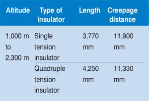 These composite long rod insulators for the hilly terrain were successfully type tested by Teestavalley Power Transmission Limited at the Central Power Research Institute, Bangalore in the year 2011. These insulators are suitable for altitude up to 2,300m, for the following impulse levels:
- Lightning impulse withstand level: 1,821 kV
- Switching impulse withstand level: 1,234 kV
- Power frequency withstand level: 799 kV
 Although the design and engineering of composite long rod insulators was carried out at the highest altitude of 2,300 m as envisaged during the planning stage, one tower was required to be constructed at an altitude of 2,600 metres due to prevailing site conditions.
To conclude, Teestavalley Power Transmission Limited has installed composite long rod insulators of length 3,770 mm and 4,250 mm with creepage distance of 11,900 mm and 11,330 mm respectively and with the basic impulse level of 1,821 kV in the 400 kV D/C quadruple ACSR moose conductor power line. It connects the Teesta III HEP in north Sikkim to the Kishanganj Pooling Station in North Bihar through Darjeeling in North Bengal with altitudes up to 2,600 metres from the mean sea level. The composite long rod insulators take care of uncertainties in the application of atmospheric and altitude correction in the Himalayan region.