
The goverment, in its drive to improve the ambient air quality throughout India, has mandated that most coal-firing power stations must fit flue gas desulphurisation (FGD) plants. In order to reduce the cost of running FGD plants, many power companies are now opting for “FGD wet stack” operation, where the flue gas exiting the FGD absorber is not reheated, and enters the chimney at a low temperature and at full water vapour saturation.
Running FGD wet stacks, while economically attractive, carry the risk of “spitting”, known as stack liquid discharge (SLD). This phenomenon can be highly problematic, with acidic droplets raining down on to the environment surrounding the power station. In serious cases, such SLD can damage private property such as cars and crops, as well as sensitive equipment within the power station itself.
A number of power stations worldwide have experienced SLD problems and, in some cases, this has resulted in a need to retroft and operate expensive flue gas reheat systems, which significantly reduce the efficiency of power production.
In order to minimise the risk of SLD, it is necessary for the power company and its designers to implement several important design principles. The following steps can address these.
Step 1: Perform a wet stack design study.
When the general geometries of the FGD absorber, the flue gas ductwork towards the chimney, and the chimney itself are known, an experienced expert should model the system to predict the behaviour of any liquids contained within the flue gas stream. The modelling must include the construction of a physical scale model. (Figure 1)
Based on the observations in the modelling phase, the expert should design a system of collection gutters and drains, placed in the flue gas ductwork and in the chimney itself, to effectively remove liquids from surfaces where they are collected. A well designed system of gutters and drains will-prevent the liquid film from re-entering the flue gas stream, minimising the dreaded SLD phenomenon.
Step 2: Adjust the velocity within the chimney to the material of construction.
When constructing an FGD wet stack, the power company and its designers have a number of materials options, including fibre reinforced plastic, titanium, high nickel alloy, flake-filled coatings and borosilicate glass block. In its 2012 “Revised Wet Stack Design Guide”, the US Electric Power Research Institute has issued recommendations of the acceptable flue gas velocity for each of these materials (Figure 2).
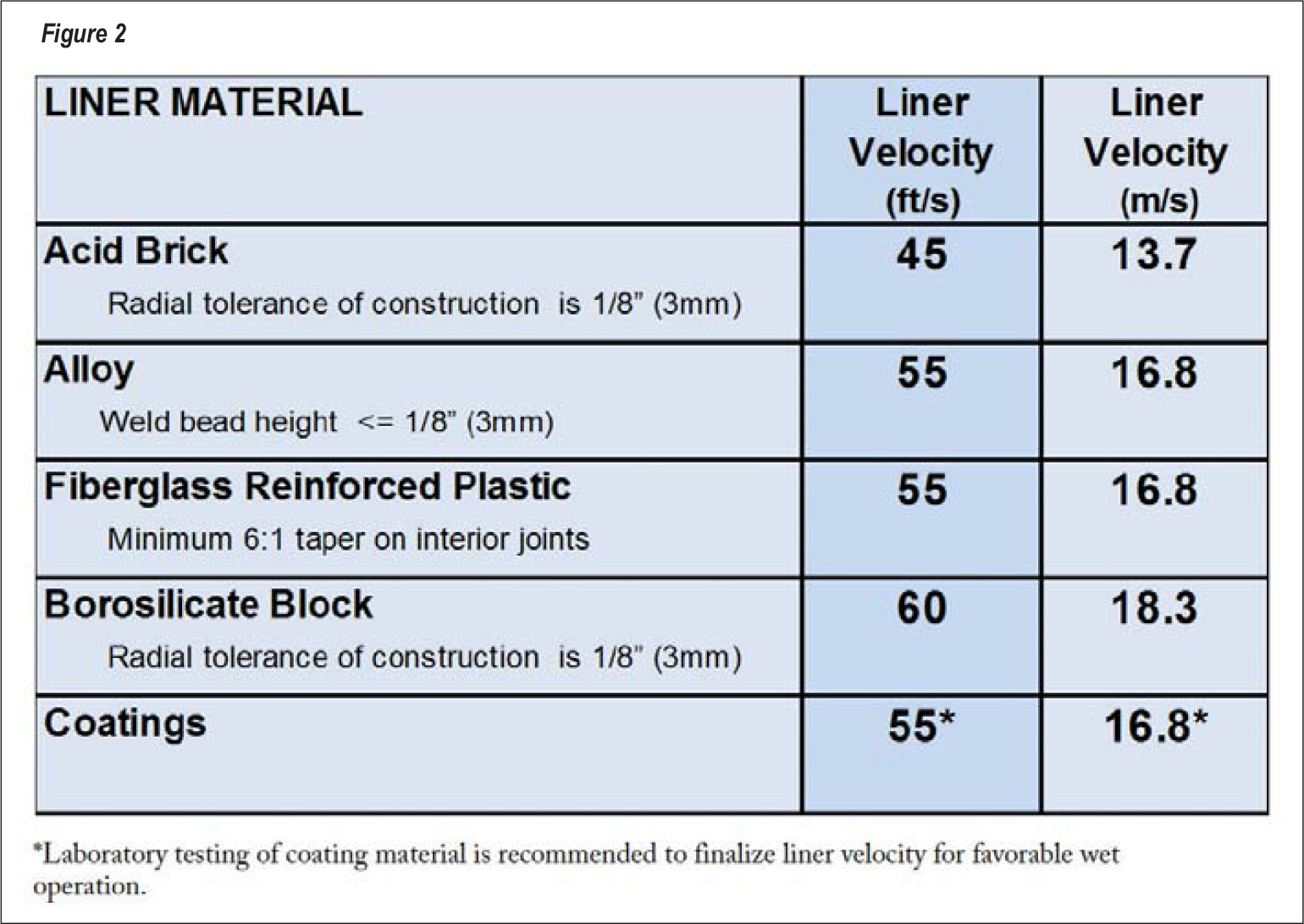
As the figure suggests, the “borosilicate block” allows for the greatest velocity in FGD wet stacks at a recommended 18.3 metres per second. It is important to understand, however, that the safe velocity for a borosilicate glass block lining can vary significantly among various manufacturers; so specific testing and certification of any specific brand is required.
In a recent development, one supplier now offers its specific brand of borosilicate glass block lining in a proprietary pattern, which allows FGD wet stacks to be run at velocities of up to 22.9 metres per second with only sporadic liquid re-entrainment. This solution is especially relevant for power companies that want to reline existing chimneys in which flue gas velocities can run higher than the 18.3 metres per second recommended for the lining in its basic form.
The special pattern can also be an attractive option for the entry zones of new chimneys, in cases where a wet stack design study indicates that higher velocities can occur locally due to gas stream imbalances.
 Step 3: Consider the use of special liquid collecting guide vanes in the chimney inlet zone.
In conjunction with the popularity of FGD wet stacks, many power companies are also opting to place FGD absorbers and newly built chimneys very closely together, keeping the length of the flue gas ducts between the FGD absorber and the FGD wet stack to a minimum. This is a good decision from an economical perspective but has a serious impact on SLD.
The reason is that relatively short flue gas ducts, especially those that do not include any turns, offer little opportunity for collecting and draining of liquids from the flue gas stream. As a result, power plants that have FGD absorbers and FGD wet stacks placed closely together are at a high risk of SLD problems.
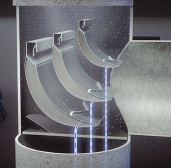
For these specific cases, power companies can now use special guide vanes placed in the bottom portion of the FGD wet stacks. These guide vanes, which are a proprietary technology, follow a form resembling airplane wings and they have a combined function of reducing stack inlet pressure loss by 70 per cent, while also catching and draining off liquid droplets contained within the flue gas stream. (Figure 3)
Conclusion
SLD from FGD wet stacks is a serious problem and it can only be prevented by strictly adhering to some specific steps. These steps must be taken at the design stage, as it is extremely difficult to address any SLD problem once it has occurred. Even with the additional cost of these special measures included, the option of FGD wet stack operation will still be the economically best choice in most cases.