
The construction of inclined pressure shafts is usually the most challenging job worldwide. When it comes to the replacement of any ruptured steel liner segment confronting heavy ingress of water from a saturated hill mass, coupled with constrained space, the difficulty level increases manyfold. This paper gives an account of the rectification works of the steel liner taken up in each of the two pressure shafts, with 3.5 metre diameter and 1.5 km length at 30 degree inclination, at NHPC’s 800 MW Parbati II (HEP) in Himachal Pradesh. The replacement of a 3 metre long steel liner in each pressure shaft was accomplished successfully through the in-house engineering prowess of NHPC’s engineers. The relentless efforts by the engineers paved the way for successful completion of rectification works and the project was made operational at part load by utilising the available water from Jiwa nallah.

The Parbati HEP (Stage II) is an inter-basin transfer type run-of-the-river scheme on the river Parbati, comprising an 84 metre high concrete dam, 31.5 km long head race tunnel (HRT), two 1.5 km long inclined pressure shafts and a surface powerhouse comprising four units of 200 MW each. During lean periods, project generation is further augmented by diverting the water of five rivulets (nallahs) – Jigrai, Manihar, Pancha, Hurla and Jiwa.
All the major components of the project, except excavation of the 2.5 km HRT with a tunnel boring machine (TBM), have been completed. Further, works related to the Jiwa nallah, including the feeder tunnel and the drop shaft, have been completed as part of the project (Fig. 1). Works on the other rivulets are at advanced stages of completion.

During the testing of machines in March 2017 and July 2017, the seepage of water in the order of 600-800 litres per minute (lpm) was observed at about 1.6 km downstream of the powerhouse. During the inspection of the HRT and pressure shafts, minor to moderate seepage was observed from gantry joints/grout holes in the HRT at a few locations and longitudinal/curvilinear cracks were observed in the left and right pressure shafts with ingress of water.
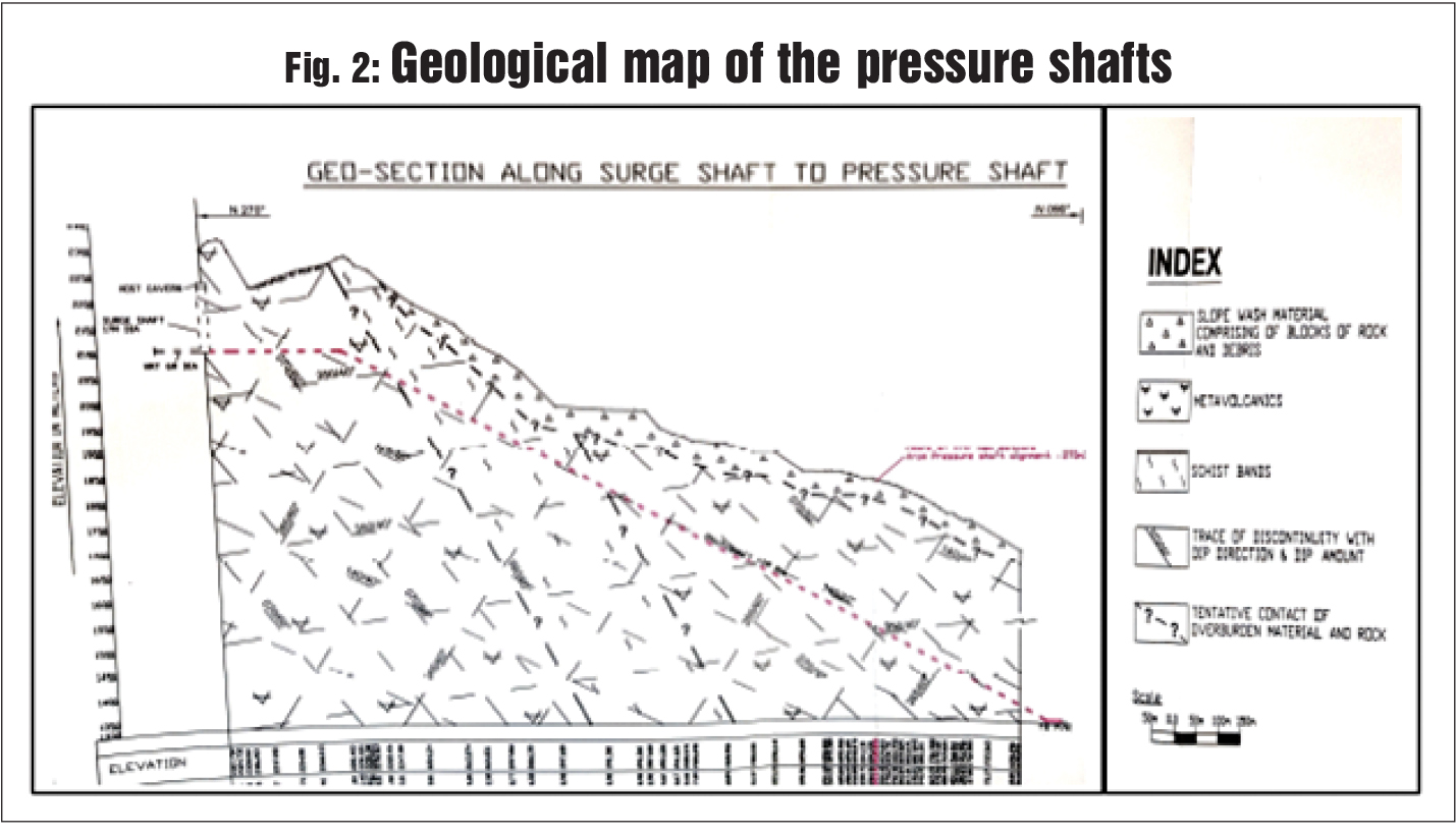
Geology of the hill mass around the pressure shafts
The hill mass along the pressure shafts consists of slope wash material comprising blocks of rock and debris in the upper layer. The outcrops indicate the dominance of metabasic rocks, slightly weathered and jointed in nature (Fig. 2).
Both the pressure shafts were excavated with a double shield TBM with excavated diameter of 5 metres to achieve a finished diameter of 3.5 metres. The shafts have bottom horizontal legs of ±300 metres, inclined portion of 1,500 metres and top horizontal portion of ±200 metres. The excavated rock was supported with 200 mm thick precast concrete segment lining with pea gravel filling. Further, the pressure shafts were steel lined with ASTM A 517 Grade F steel of variable thickness (16 mm to 42 mm), followed by M25 grade 400 mm thick self-compacting backfill concrete in between (Fig. 3).

Design parameters of the steel liner
The steel liners have been designed for internal water pressure, corresponding to FRL (EL 2,198 metres) with water hammer effect for EL 2,234.3 metres in the surge shaft without considering any rock participation2. Over and above 1.5 mm, corrosion allowance has been considered. Further, the liners are designed for external pressure corresponding to the reservoir level or the ground level vertically above the pressure shaft invert, whichever is less. An initial gap between the steel liner and concrete has been assumed as 0.0007R, which is equal to 1.22 mm; however, if the initial gap between the liner and concrete exceeds the assumed value, the ferrule may reach critical buckling pressure at a value of 0.0035R, that is, 6.1 mm, which may lead to failure of plates.
Failure of plates and analysis
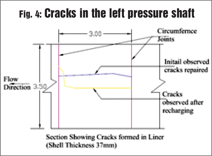
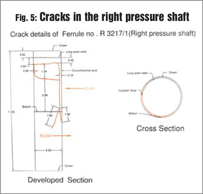
On physical examination of both the pressure shafts, it was found that one liner segment (3 metres long) in the left pressure shaft at about 480 metres above the bottom elbow (EL ± 1,575 metres) had longitudinal cracks. Similarly, in the right pressure shaft, one segment liner at about 240 metres above the bottom elbow (EL ± 1,460 metres) (Figs. 4 and 5) had curvilinear cracks.

Moderate seepage in the left pressure shaft and heavy ingress of water in the right pressure shaft was observed through ruptured areas. The ferrules in the right pressure shaft were slightly bent inwards and there was ingress of water at about 7 ~10 kg per cm2. The presence of one natural subsurface stream in the vicinity of the ruptured liner was also noticed during the construction stage. The pattern of seepage observed in the right pressure shaft over a month’s time during the lean season indicated a steady discharge of the order of 250-300 lpm.
The water conductor system was also emptied during this period to rule out any possibility of charging of the surrounding hill mass due to seepage from the HRT. The critical buckling of the steel liner was taken care of at the design and model study stages and therefore failure due to inadequate plate thickness was ruled out.
Test result of plates
The sample of the ruptured ferrule was sent for testing to reputed labs, which indicated the failure of the sample in meeting the tensile test and Charpy V-notch impact test (Table 1).

Additional strengthening of the pressure shaft
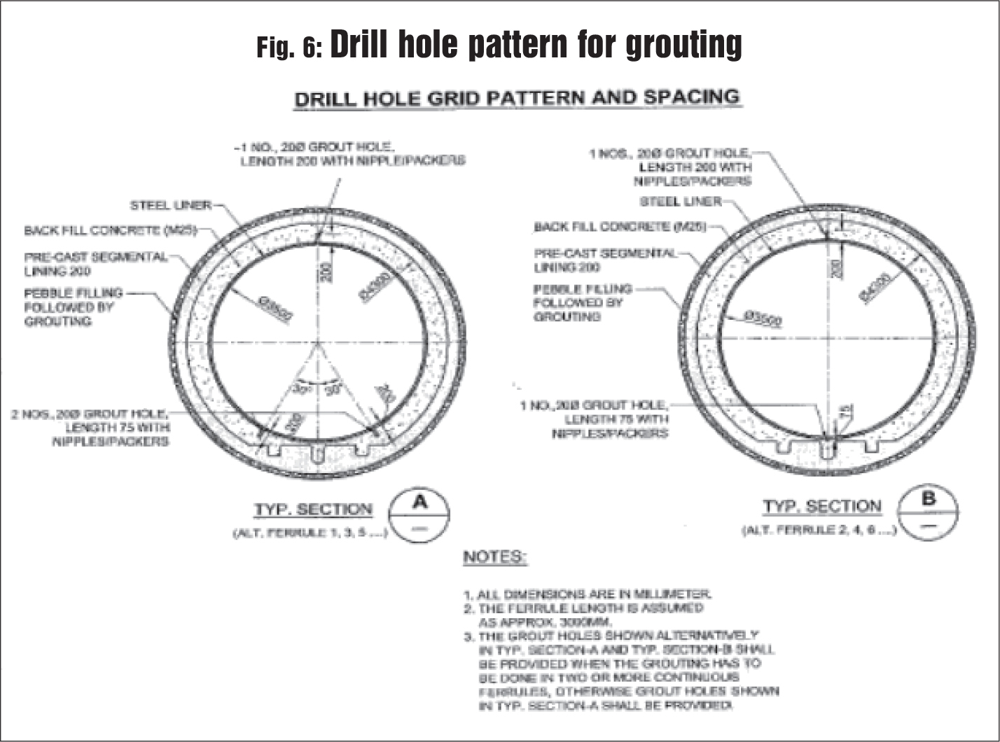
Having established the reasons of failure as inadequate structural properties in one lot of material used in the erection of the liner, the option to either reinforce the defective liner or replace the same was discussed. Further, to take care of any shrinkage in the self-compacting concrete behind the steel liner resulting in minor gaps, it was decided to first carry out additional consolidation grouting in the full length of the pressure shaft as per the drawing issued by the design division (Fig. 6).
Rectification of damaged ferrule liners
The decision of reinforcement of the ruptured ferrule vis-à-vis replacement with a new liner was based on the merits and demerits of both the options. Reinforcement of the existing liner could have been easier; however, maintaining the homogeneity of liners was a major challenge and stability in the long run was sceptical. Accordingly, it was decided to replace the liner, which involved cutting of the existing plates, tackling seepage from the precast segment, installing new liners, moisture-free welding, etc. For smooth replacement of the damaged ferrule, grouting was carried out through two grout pumps in stages, from bottom to top. In the left pressure shaft a total 120 holes were drilled and grouted with OPC in a length of about 1,500 metres. Additional grouting was also carried out by using microfine cement simultaneously to ensure packing of voids on account of shrinkage, if any. The total grout intake in the left pressure shaft is mentioned below.
– OPC – 26.40 tonnes
– Microfine cement – 18.62 tonnes
– PU (single component) – 0.85 tonnes
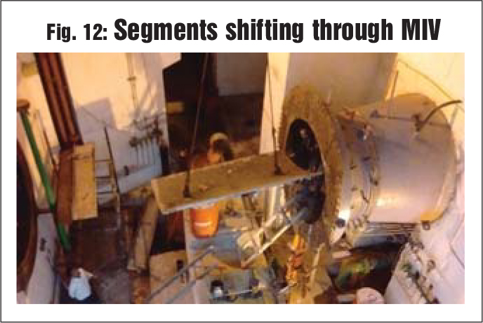
The seepage in the left pressure shaft was tackled with PU grout before cutting of plates through a portable electrically operated PU pump capable of injecting grout up to 60 bars. For shifting new plate segments inside the pressure shaft, dismantling of the main inlet valve (MIV), arrangement of a 45 T capacity Winch, fabrication of a special trolley for transportation of the steel plate segment and deployment of technical crew for its erection was done at the site. A total of 11 pieces plates, with approximate weight of 1,000 kg each, were placed in the left pressure shaft.
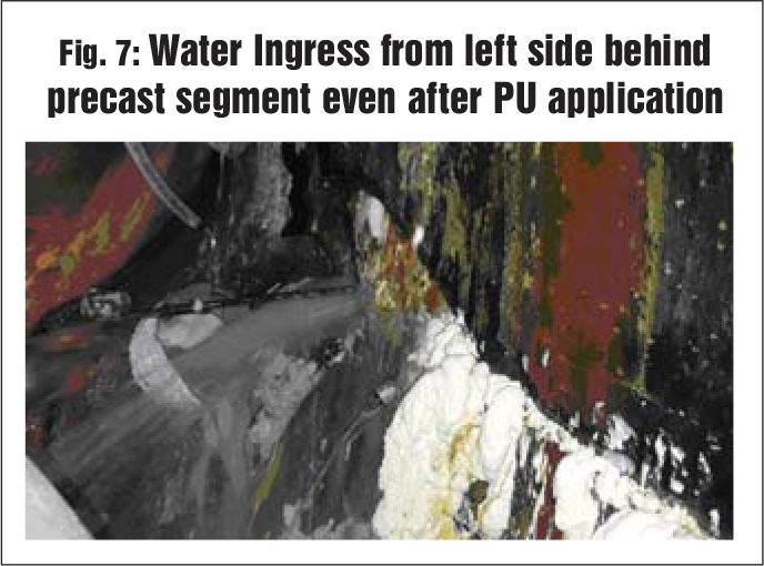
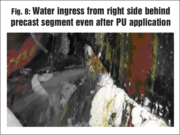
Rectification of the right pressure shaft was more challenging due to huge seepage all along the length, particularly at the location of the ruptured ferrule. There was continuous ingress of water in the order of 350 lpm from the ruptured liner. Due to extensive seepage all across the circumference, moist conditions prevailed inside the liner. Under such conditions, neither electrically operated cutters nor gas cutting could be carried out as single-component PU foam grouting was done to arrest the seepage water before the cutting of plates. As seepage could not be eliminated even after the application of single-component PU, water was channelised by installing gate valves. The PU material used in the grouting was fire resistant but its foam started burning at flashpoint; this was a major impediment and a safety hazard in the cutting of plates (Fig. 7); however, this was overcome by adopting a careful cutting pattern. After the cutting of plates, chunks of backfilled concrete/grouted microfine cement of size 1.24 x 0.60 x 0.40 metres got dislodged, exposing the precast segments and resulting in the ingress of seepage water through joints of precast concrete segments (Fig. 8).
After rechannelising seepage water through pipes and gate valves, the cutting of the remaining steel liner and sequential re-erection of liners was done. However, due to a continuous seepage of water all along the ruptured ferrule, the root welding of plates failed every time. To arrest seepage, heavy grouting with normal OPC/microfine cement and PU was done but root welding failed repeatedly and by this time six segments were already placed (Fig. 9).
The “Broco” make electrodes, being used by the navy and suitable for underwater welding, were also tried in root welding. Theses electrodes produce weld with low porosity while allowing deeper welding equivalent to E7018 grade electrodes recommended for root welding and also compatible with E11018 grade electrodes recommended for final welding. However, even these electrodes could not succeed due to high fumes and vapour from beneath the liners, leading to cracks within 24 hours.

Challenges faced in rectification under flowing water conditions
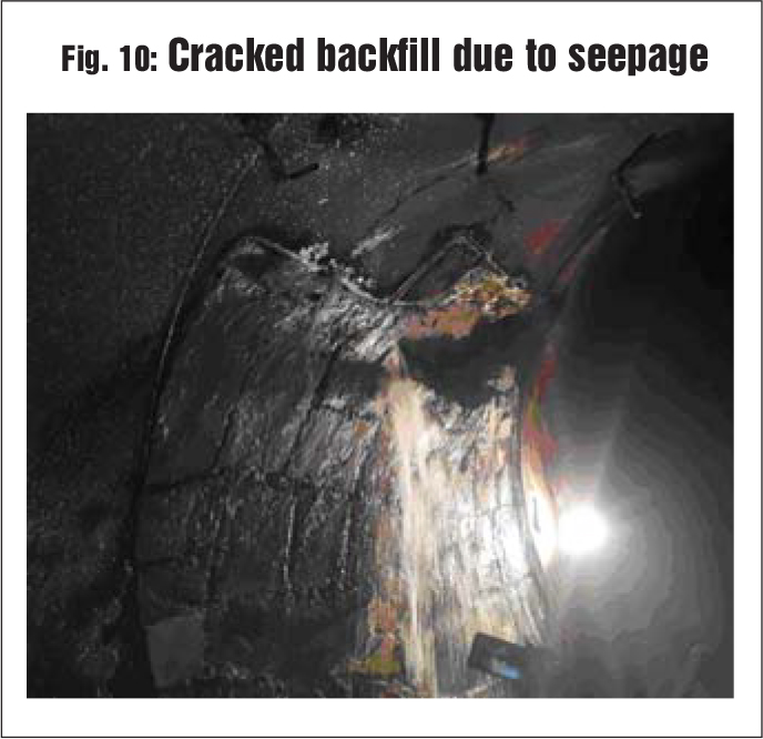
The operation was very challenging due to the uneven seepage pattern behind ferrules. At some points, seepage was encountered at very high pressure even after multiple grouting. Single-component PU material was not effective at many places due to non-foaming observed even after several days of grouting. The resin remained in liquid form and used to eject with high pressure during inspection. Meanwhile, seepage in the order of 250-300 lpm continued from behind the precast segments. Efforts to stop this inflow by using the single-component PU grout at high pressure resulted in the development of cracks in the backfill concrete all across the circumference, indicating interconnections of the water path. This led to apprehensions that a huge concrete mass could fall on the manpower working below on the trolley and pose a safety hazard (Fig. 10).
The project was running short of time as the monsoon season was about to begin and any delay in completion could result in further charging of the surrounding hill mass, resulting in increase in seepage and jeopardising the success of the entire work. Therefore, in order to plug the holes and carry out the replacement of new liners, single-component PU material was used. The pattern of consumption of the material in grouting indicates huge voids in the vicinity of the liner where OPC with microfine cement consumption was also higher than in other stretches. The huge quantity of OPC and microfine cement grout intake near the ruptured ferrule also means the presence of larger void spaces behind the precast concrete segment.
The commonly available grouting pumps in the market are pneumatic machines; however, these could not be deployed at this site due to non-practicability of providing air line for such long distances. The GRACO Tough Tek Microfine Cement Grout Pump with capacity to pump at 60 bars was improvised with electric motor for microfine cement grout. Further, the GRACO TEXSPRAY PU Grout Pump was improvised by installing two pistons for using two-component PU material with the facility of mixing at the nozzle tip and capacity of delivery up to 10 lpm.
Silicate-based PU material was used to impart strength and to achieve early strength due to its property of early gel formation, so as to fill the cavity behind the precast segment, where all previous efforts of grouting with microfine cement could not succeed. As the plates were in contact with the backfill material, cracks were noticed after root welding due to minor seepage from the area already grouted, thus requiring the relocation of the already erected six ferrules and channelisation of seepage water. In order to eliminate even the slightest possibility of moisture, work was carried out in the following steps:
- Channelisation of water in each ferrule one by one.
- Re-erection of the steel segment, extracting the liners already placed in position by shifting these massive 1.6 tonne plates inside the shaft, by almost 102o-105o clockwise circumferentially, using chain pulley blocks (Fig. 11).
- Drying up the area through grouting with microfine cement and sodium silicate (variable dosing of sodium silicate 15-20 per cent by weight of cement).
 This could be achieved by improvising a small portable electric pump for carrying out microfine grout by limiting the injection pressure within 1.5 MPa (15 bar) and two-component PU for sealing the moisture as per site conditions to achieve welding of the steel segment. For grouting of the entire right pressure shaft, a total of 259 holes were drilled with material consumption as below:
– OPC – 220.85 tonnes
– Microfine cement – 31.75 MT
– PU (single component) – 5.64 MT
– PU (two component) – 3.95 MT
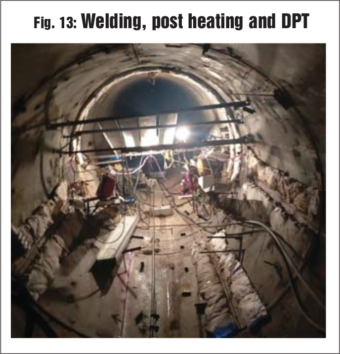
The quantum of grouting with cement (OPC/microfine) is approximately six times the grouting in the left pressure shaft and more than 10 times in terms of PU; this indicates the unpredictable underground conditions prevalent in the vicinity of both the shafts having a lateral cover of barely 50 metres from each other. The total time taken for the rectification of the right pressure shaft was about 13 months as against the four months time taken in the left pressure shaft. The segment shifting process through MIV and the welding and post heating process are depicted in Figs. 12 and 13 respectively.
 Conclusion
Since the test results of the damaged ferrule of a particular lot of ASTM Grade plates of one particular heat number were found to have lesser strength parameters, that is, tensile strength and Charpy V-Notch Test Values (Table 1), the probability of the ferrule reaching critical buckling pressure and expansion beyond yield stress could be one of the reasons for the failure of the plates. Further, the quantity of grout intake indicated gap/voids between the liner and precast segments and behind the precast segment in the pea-gravel, leading to the displacement of the precast concrete segments; however, it could not be ascertained.
The rectification of the left pressure shaft was successfully completed in August 2018 and has been put under operation thereafter. The rectification of the right pressure shaft was completed successfully in July 2019 and has been put to use. Since then the project is operating successfully and has generated approximately 380 MUs of cumulative energy till July 2020.
Learning
The project execution team continuously strived for innovative methods and relied on the famous Japanese approach “Kaizen” for process improvement during rectification, so that the criticality of work and day-to-day challenges could be overcome by thinking out of the box. This led to successful accomplishment of rectification works, helped in skill development and built the confidence of the in-house team in carrying out repair works under such extreme conditions.
(Disclaimer: The views expressed in this paper are of the authors and not those of the NHPC management.)
1 Investigation by the in-house geotech division of NHPC
2 In-house design of the NHPC Design Division.
3 Dimitrios Kolymbas, Tunnelling and Tunnel Mechanics: A rational approach to tunnelling.
4 Based on an independent test conducted by TCR Advanced Engineering, Vadodara.
5 Test results exceed the requirements of the American Welding Society Specification D3.6-99 for Class B underwater wet welds. Yield strengths typically exceeding 70 ksi and tensile strengths exceeding 80 ksi.
6 Tam pur 116 (Normet make) two-component, silicate modified, solvent-free, semi-flexible polyurethane injection resin having properties of rapid stabilisation and structural integrity, with strengths of more than 30 MPa.