Fossil-fired power stations form the backbone of the power industry in most countries. Due to increasingly strict government regulations in both developed and developing countries, the environmental impact of these power stations has to be ever further minimised. At the moment, it is customary for these power stations to be equipped with flue gas desulphurisation (FGD) plants, and the use of such plants has a profound effect on power station chimneys. On the one hand, operating conditions become more aggressive due to low temperature, acid condensing operation. On the other hand, the height re-quirement for chimneys is reduced thanks to reduced emissions and pollutant ground level concentrations.
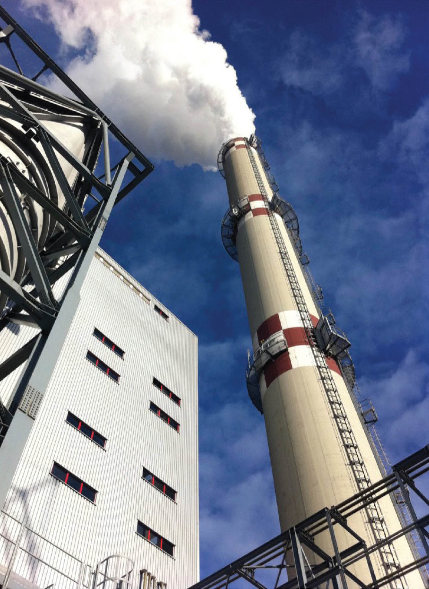
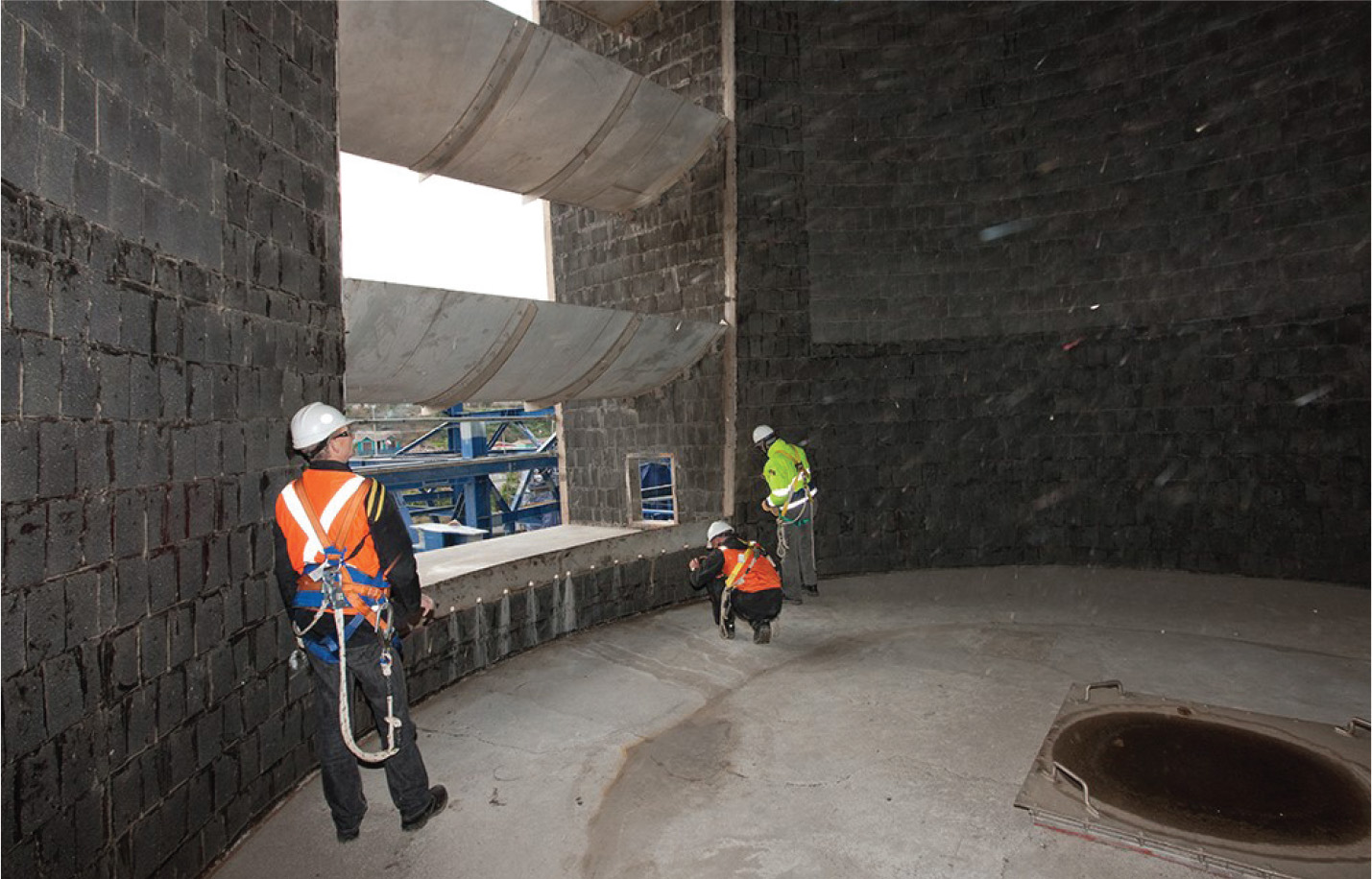
In their efforts to deal with the huge cost of FGD operation and other environme-ntal regulations, power companies increasingly choose to construct new chimneys in accordance with the New Chimney Design (NCD), a design that eliminates the use of any internal flue and instead uses a slender concrete shell protected directly by a borosilicate glass block lining (BGBL). We shall discuss how power companies can specify the technical properties and requirements for NCD chimneys to ensure that they are constructed in a safe, reliable and durable manner.
Key areas to be covered by technical specification
In order to ensure that NCD chimneys are properly designed and constructed , allowing these chimneys to achieve their full safety, reliability and durability, the following aspects need to be considered:
- The owner must specify all operating, meteorological and seismic conditions to be encountered by the new chimney.
- The specification must also include the owner’s requirement for allowable pressure losses.
- Considering the key role of the lining as both chemical and thermal protection, the required product quality, installation quality, track record and guarantee for the BGBL must be clearly described.
If the new chimney is to be operated as an FGD Wet Stack, that is, meant to carry low temperature, water saturated flue gas, this should be addressed in the specification and the internal design of the chimney must meet all requirements for safe collection and draining of flue gas condensates.
- Considering that the formation of verical cracks is a key performance indicator for NCD chimneys, the specification must provide clear limits for the allowable width of these cracks.
- Finally, if the NCD chimney is to be located in a seismically active area, the specifications must impose a requirement on the vertical cracks that can be allowed in the NCD concrete shell following a seismic event.
A closer look at each of these six key areas…
Operating, meteorological and seismic conditions
While the listing of meteorological and seismic conditions is a well-established and mostly standardised practice, a meaningful listing of operating conditions is sometimes difficult for power companies that have not previously operated chimneys downstream from FGD plants.
The most important question that needs to be addressed in any specification is whether the NCD chimney will be operated as a “wet” or a “dry” stack. If the flue gas stream is fully treated in a wet FGD plant and then released to a chimney in a water-saturated, non-reheated condition, the NCD chimney is a wet stack (formally, an “FGD Wet Stack”). The chimney, including its lining and all of its internal structures, must then meet with the onerous requirement of wet FGD stack operation.
If the flue gas stream is only partially desulphurised, or treated in a semi-dry FGD system, or reheated by some form of heating equipment (such as a rotary gas-to-gas heater) the flue gas stream entering the chimney will be above its water dewpoint and the requirements for the lining and the internal structures will be different.
Another important consideration is whether the flue gas volume of the current design is indeed the volume that can be reliably expected over the service life of the power station. In recent decades, many owners have found that the flue gas volume entering into a chimney can vary as a function of fuel quality, boiler fouling and power production demands.
Finally, should there be any risk of high temperature upsets, these should be clearly specified as well, especially since such events may lead to overheating of the chimney structure, which may then result in the formation of wide vertical cracks. Proper engineering of NCD chimneys can take into account, and eliminate, the risk of such crack formation even during thermal upsets.
Pressure losses
Pressure losses in the flue gas path will directly impact the energy consumption of the power station itself. An inefficient design for an NCD chimney can burden the power station with excessive energy consumption throughout its operational life, considerably reducing the power output and revenues of the plant.
As a general principle, the technical specification for an NCD chimney must instruct contractors to design NCD chimneys for minimised pressure losses. The primary requirement must be that NCD chimneys should have a cylindrical shape to the largest extent technically possible, avoiding any conicity, especially in areas above the flue gas inlet.
Furthermore, the technical specification must instruct bidders that, if effective, the NCD chimney shall use design modifications to reduce pressure losses, including so-called top diffusors and internal guide vanes. It should be noted that if the NCD chimney is an FGD Wet Stack, such guide vanes must meet with specific requirements.
 Internal lining system
When used in an NCD chimney, the internal BGBL lining plays a key role, protecting the concrete chimney shell both against acidic condensate and against thermal stresses. Consequently, the technical specification for the NCD must pay special attention to the quality of the internal lining system.
First of all, it is essential that any lining system used in the NCD application be long-term resistant to the operating conditions that will prevail once the NCD becomes operational. For example, if an NCD would operate under FGD Wet Stack conditions, it must be certain that the lining will retain all of its physical properties when exposed to significant quantities of dilute acidic condensate.
Secondly, the specification should require that all of the installation works of the selected lining system are executed under supervision of experienced quality assurance inspectors, and that all inspection results are carefully logged to confirm that the installed lining will reach its full technical capabilities.
In order to create an objective basis for accepting or rejecting candidate lining systems, it is recommended to include clear track record requirements in the specification. For example, the specification may state that “…the supplier of the selected lining system must demonstrate successful experience of not less than X years under the operating conditions listed in this specification.”
Finally, it is important that a lining supplier should commit to the quality of their lining system by issuing a long term guarantee, and it is recommended that such a guarantee should be a single-source one, where the same party is responsible for the quality of both the lining material and the installation works.
Requirements related to FGD stack operations
In recent years, many power companies have decided to operate wet FGD systems for the entire flue gas volume of their fossil-fired units while not applying any form of reheat. Consequently, the chimneys of these power stations are operated as FGD Wet Stacks, carrying low temperature, water-saturated flue gas.
When specifying an NCD chimney for an FGD Wet Stack application, the owner should take special care to include all the technical requirements for operating the NCD chimney under these specific conditions.
First of all, the specification should ensure that the gas flow velocity in the chimney cannot, under any circumstances, exceed the gas flow velocity where a risk of stack liquid discharge (spitting of acidic droplets from the top of the chimney) exists.
This critical velocity is usually established by testing and observing the behaviour of a liquid stream on a vertical test panel of the proposed lining system. It is recommended that the expected flue gas velocity in the NCD chimney should be calculated with a proper safety margin to allow for future gas volume increases.
Secondly, it is important that any NCD operating as an FGD Wet Stack is equipped with a well-designed system for the collection and draining of flue gas condensates. Any gutters and drains used for such a system should be fabricated in a material, metallic or otherwise, that has demonstrated resistance to the FGD Wet Stack operating environment.
Finally, the technical specification should mention that the use of guide vanes within the chimney is not allowed, considering that guide vanes in an FGD Wet Stack act as collection points for acidic droplets, resulting in uncontrollable stack liquid discharge. An exception may be made for special guide vanes that have been developed for collection and draining of liquid condensates.
 Performance criteria for NCD concrete shell
Vertical cracks will naturally occur in the concrete shell of any chimney. The width of such cracks is controlled by a steel reinforcement within the concrete structure, provided that such reinforcement has been correctly designed and executed.
Consequently, the width of vertical cracks in the concrete shell of an NCD chimney is a key performance criterium and it is suggested that, using a correct design and a high quality, thermally insulating lining system, this width can be limited to a maximum of 0.3 mm.
Width of vertical cracks following seismic events
NCD chimneys have properties that are naturally favourable for resisting seismic events, considering that they are lightweight structures protected by lightweight lining systems and that, due to the absence of any significant internal structures, seismic events cannot create any damaging point loads.
It is nevertheless of great importance that the technical specification for an NCD chimney shall also demand that the structure is not materially damaged in a seismic event. By using a correct design for the NCD chimney, it should be ensured that even in the event of an earthquake, the width of vertical cracks in the chimney shell does not exceed 0.3 mm.
Conclusion
NCD chimneys are an attractive option for power stations operating FGD equipment, allowing the owner to significantly reduce construction cost as well as chimney footprint and chimney construction time schedule.
In order to realise these benefits in a safe and durable manner, it is essential that the owner use a strict and detailed specification, listing the specific properties and requirements for this chimney type.
The authors are currently preparing a sample specification that may be used for this purpose.


By Albert de Kreij, Hadek Protective Systems BV; Andreas Harling, Constructure GmbH; and Markus Rost, Constructure GmbH
