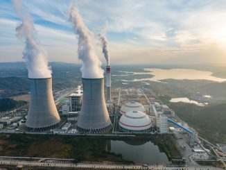

The coal-based thermal power sector is responsible for a significant share of industrial emissions in India. As per Centre for Science and Environment estimates, the coal-based power industry accounts for as much as 45 per cent of sulphur dioxide (SO2) emissions in the industrial sector in India. The absence of any definitive SO2 emission regulations for the power sector prior to the tightening of emission norms in December 2015, has led to the limited adoption of SO2 emission control technologies. The low sulphur content of Indian coal is one of the reasons for the lack of focus on the control of SO2 emissions. However, under the emission norms issued in December 2015, the SO2 emission limit for thermal power plants (TPPs) was determined. For all TPPs installed by December 31, 2016 with a capacity of less than 500 MW, the limit is 600 mg per Nm3 (milligrams per normal cubic metre), and for those with a capacity of 500 MW and above, the limit is 200 mg per Nm3. Meanwhile, for all plants installed after January 1, 2017, the SO2 emission limit was specified as 100 mg per Nm3 only, irrespective of the capacity. These regulations, coupled with the widely available pollution control technologies, are expected to help lower SO2 emissions from the power sector.
The two basic approaches for controlling SO2 emissions from TPPs are to reduce the sulphur content in the fuel through fuel blending or switching, or to remove SO2 directly from the flue gas. Flue gas desulphurisation (FGD) is a mature technology for controlling SO2 emissions and is effective for a wide range of coal qualities and under various operating conditions. Some of the techniques for removing SO2 from flue gas are wet FGD, dry FGD, circulating dry scrubber (CDS) and dry sorbent injection (DSI). The choice of emission control technology depends on various factors such as the scale of process, sulphur content in the coal, and the availability and cost of reagents.
Wet FGD
Wet FGD is the predominant technology used across the world for reducing SO2 emissions of TPPs. This can be attributed to its high efficiency and compatibility with various types of coal such as anthracite, bituminous, sub-bituminous, lignite and brown coals. The technology can remove above 90 per cent of SO2 from flue gas.
Wet FGD uses a calcium or sodium-based alkaline reagent such as limestone, sodium carbonate, magnesium carbonate or ammonia in a solution or slurry form. Limestone being cheaper and more abundant than other alkalis is the most commonly used reagent for the process. In wet FGD systems, the alkali and flue gas are brought into contact in a spray tower where the alkali reacts with the SO2 in the flue gas to produce a mixture of sulphite and sulphate salts. The sulphite and sulphate salts thus produced precipitate, depending on the relative solubility of the different salts present.
Dry and semi-dry FGD
The dry FGD process is similar to the wet FGD process, except that it uses a dry solid reagent rather than a solution reagent. Spray dryer absorbers (SDA) are an example of a dry FGD system. In an SDA system, lime slurry is atomised and sprayed into the hot flue gas to absorb the SO2 and other acid gases. The SDA cools the flue gas to 65-75 °C, before the gas passes through a fabric filter so that metals with vapour pressure at flue gas temperature are present more in the solid state and get easily captured in the fabric filter. The resulting dry material, which includes reaction products and fly ash, is collected in a downstream particulate control device, typically a fabric filter or sometimes an electrostatic precipitator (ESP).
While dry FGD systems are capable of removing only 70-90 per cent of SO2, they entail lower capital and operating costs, and require less energy, water and maintenance. The dry material produced can be recycled back into the lime mixture owing to its alkaline nature, thus minimising the lime requirement.
Circulating dry scrubber
Circulating dry scrubber (CDS) technology is a type of dry FGD system, which is useful in cases where the sulphur content in coal is medium to high. The CDS process uses a fluidised bed to bring the reagent (typically hydrated lime) in contact with the SO2 in the flue gas. Water spray is introduced into the fluidised bed separately from the dry reagent to enhance the performance of the system by optimising the surface moisture content of the lime. The mixture of the remaining products (calcium sulphite/ sulphate), unused lime and fly ash is carried to a downstream particulate collector and is separated from the gas stream. The waste can be mixed with fresh calcium hydroxide and used again in the process.
CDS can remove up to 98 per cent of SO2, depending on the conditions of the application. The use of an integral jet fabric filter can further reduce emissions. CDS systems are also less expensive than wet FGD systems and they do not require a wastewater treatment facility since the process creates a dry solid by-product. Another form of FGD is the semi-dry FGD system, wherein the sorbent is introduced as aqueous slurry, but the water content is controlled so that the slurry dries completely in the flue gas ductwork and the by-products are dry solids.
Dry sorbent injection
Dry sorbent injection (DSI) is the least expensive emission reduction technology. It involves the injection of a dry sorbent such as sodium bicarbonate or lime into the ductwork from the boiler. SO2 reacts directly with the dry sorbent, and the dry product is collected in a downstream particulate control device. Since the system does not require a separate absorber vessel, the capital costs are considerably lower. However, the low capital costs are partially offset by lower reagent utilisation, which results in higher operating costs for equivalent SO2 removal. Dry injection systems can typically achieve removal efficiencies of 50-70 per cent, depending on the conditions of the application.
Conclusion
There are a few concerns pertaining to FGD installation. One, the sulphur captured by FGD systems is in the form of calcium sulphite and calcium sulphate, or gypsum. This creates a greater problem of disposal than fly ash because cement and white board manufacturers require more pure fly ash than gypsum. Thus, the unutilised gypsum has to be disposed of, increasing the demand for already scarce land. Also, limestone is the key raw material required for FGD. The operation of FGD systems using limestone also adds to the carbon dioxide emitted by power plants as limestone decomposes into calcium oxide and carbon dioxide. Another challenge is the high costs associated with pollution control equipment. As per industry sources, the installation of partial FGD equipment to comply with the SO2 emission norms, units with less than 500 MW of capacity would require an estimated Rs 2.5- Rs 3 million per MW. Meanwhile, units with a capacity of 500 MW and above would require full FGD to meet the SOx emission norms, which would entail a capital investment of Rs 5 million-Rs6 million per MW.
Units of less than 500 MW installed between 1990 and 2016 (54.2 GW capacity) need to meet the SO2 norm of 600 mg per Nm3. These units may choose economical options such as partial FGD or sorbent injection. Units of more than 500 MW of capacity installed between 1990 and 2016 (98.3 GW capacity) need to install limestone-based wet FGD or lime-based dry FGD, depending on the raw material and water availability.
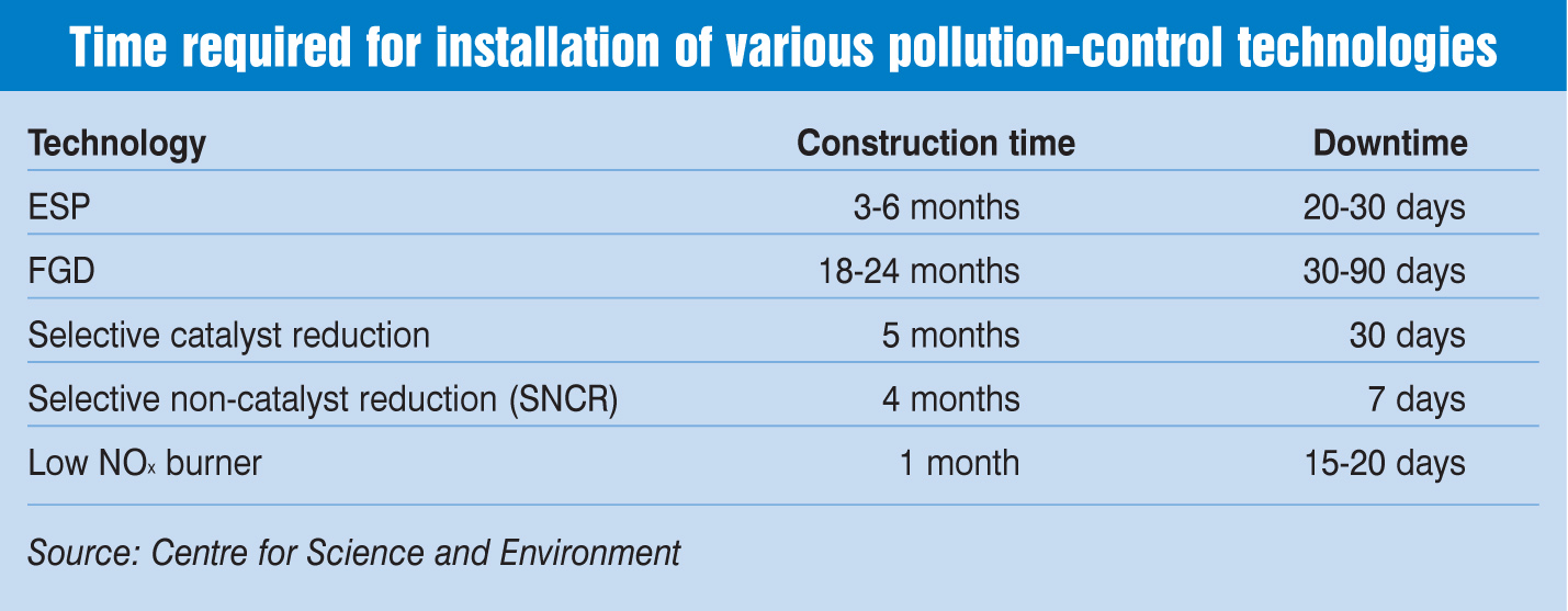
According to developers, apart from high costs, a key challenge for FGD installation pertains to time. FGD is regarded as one the most time-consuming processes, taking up to two years. Thus, developers have sought extension in meeting the new standards. Net net, while the solutions to control thermal power plant emissions are desirable from an environment point of view, it is essential to balance the interest of all stakeholders as well.