The rapid expansion of transmission and distribution networks, coupled with the growing deployment of underground cables and advanced conductors, has increased the need for robust testing and measurement practices. Cables and conductors are exposed to a range of electrical, mechanical, thermal and environmental stresses throughout their service life, making their reliability critical to the safe and efficient operation of the power system. To ensure dependable performance and minimise the risk of failures, these assets undergo a variety of tests during manufacturing, installation and operation. Such testing helps verify compliance with technical specifications, assess long-term reliability and identify defects before they affect system performance.
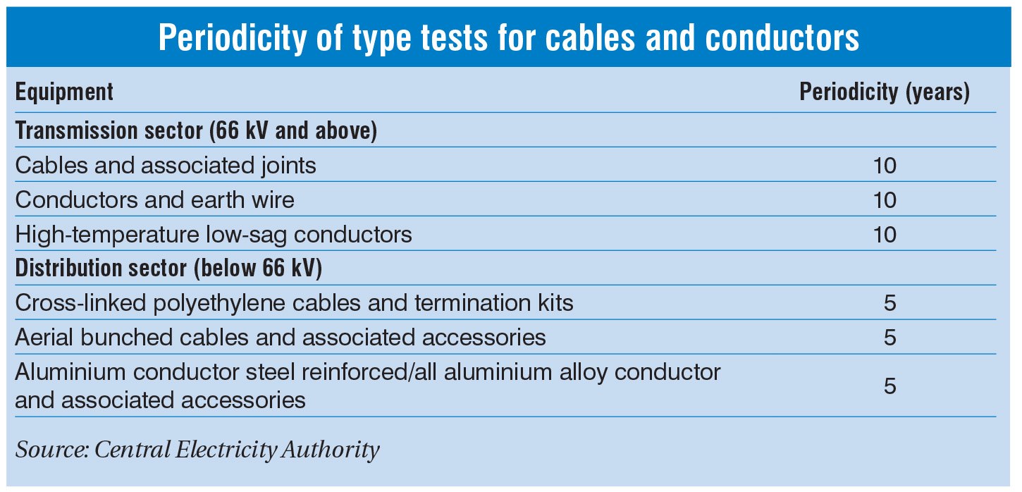
Recognising the importance of standardised testing practices, the Central Electricity Authority issued the guidelines for type tests for major equipment in the power sector in January 2026. Under the guidelines, type test reports for transmission equipment operating at 66 kV and above, including cables and conductors, remain valid for 10 years. For distribution-level cables, conductors and related accessories, the validity period is five years. The guidelines also require type tests to be repeated whenever there are changes in design, materials, manufacturing processes, technology or applicable standards.
Tests for cables and conductors
Electrical performance tests: These tests verify the ability of conductors to carry current efficiently and maintain circuit integrity. One of the primary tests is the conductor resistance test, in which DC resistance is measured at 20 °C using a micro-ohmmeter. The measured value should remain within standard limits to minimise transmission losses and heat generation. Continuity testing is also carried out to confirm that the current path is intact and free from breaks or unintended disconnections. A low resistance indicates proper continuity. Another important assessment is the voltage drop test. This test compares voltage levels at different points along a cable or circuit under load conditions to determine the reduction in voltage caused by conductor resistance and impedance.
Construction tests: These tests confirm that cables and conductors comply with specified design and manufacturing requirements. A key test is the diameter test, which measures the conductor diameter, insulation thickness and overall cable diameter and compares them against prescribed values. These parameters affect electrical resistance, current-carrying capacity and compatibility with connectors and accessories. Another important test is the stranding test, which verifies the number and dimensions of individual strands within a conductor against design specifications. Proper stranding ensures the required flexibility, mechanical strength and electrical performance. The lay ratio test evaluates the relationship between the strand helix length and cable diameter. This helps manufacturers achieve an optimum balance between flexibility, durability and resistance to mechanical stress, thereby improving long-term conductor reliability.
Mechanical performance tests: To assess the ability of cables and conductors to withstand the stresses encountered during installation and operation, an important test is the tensile and elongation test. A tensile testing machine pulls the sample until it breaks, and the elongation should typically be at least 100-200 per cent, depending on the material. Another test which is commonly performed on aluminium wires is the wrapping test. This test is used to assess the ductility of the material. In this test, the wire is wrapped around its own diameter, partially unwrapped and then rewrapped. If the wire completes the procedure without cracking or breaking, it is considered sufficiently ductile to withstand the twisting and bending encountered during manufacturing, installation and service.
Insulation tests: To evaluate insulation and shielding, a key test is the high voltage or dielectric strength test. In this test, a specified AC voltage is applied between the conductor and the grounded screen or water bath for five minutes, and no breakdown should occur. It verifies the cable’s ability to withstand voltage surges, switching transients and ageing-related stresses. Another important test is the insulation resistance test. During this test, a 500 V DC megger is applied for low voltage cables or higher for high voltage cables, and the insulation resistance is recorded. For medium voltage cables, very low frequency testing is widely used to detect water-tree degradation and microscopic defects. Additionally, the partial discharge (PD) test helps detect small electrical discharges caused by localised insulation weaknesses. A test voltage is applied and the discharge level should remain below 10-20 picoCoulombs.
 Thermal and fire resistance tests: These tests assess a cable’s ability to withstand high temperatures and fire without compromising safety or performance. An oven ageing test evaluates the thermal stability of insulation and sheathing. After heating, the cable should retain at least 70 per cent of its tensile strength and elongation. A heat shock test checks for cracking after exposure to high temperatures, while cold bend and cold impact tests verify flexibility and durability at temperatures ranging from -15 °C to -40 °C. Fire performance is further assessed through a flame-retardant test, which ensures that the cable self-extinguishes and limits flame spread. Other tests include the smoke density test to measure smoke generation and the halogen acid gas emission test for low-smoke, zero-halogen cables to assess the acidity and conductivity of combustion gases.
Diagnostic tests: Diagnostic tests help assess cable condition, estimate remaining service life and identify defects before failures occur. One of the most widely used methods is the tan delta test, which uses a very low frequency AC source to measure dielectric losses in the insulation. The test can detect ageing, moisture ingress and contamination, allowing timely maintenance or replacement. Sheath integrity is also checked to identify surface defects such as pinholes. During manufacturing, an inline high voltage spark test ensures that the sheath is free from defects. In addition, time-domain reflectometry (TDR) is used to detect and accurately locate cable faults by analysing reflected electrical signals.
Reliability tests: To assess reliability over service life, cables undergo a water penetration test. This test checks resistance to longitudinal water ingress by subjecting the cable to water pressure for 24 hours. Similarly, the uniformity of zinc coating test evaluates the protective coating on galvanised steel wires through repeated immersion in a copper sulphate solution. The absence of copper deposits indicates adequate coating uniformity and corrosion protection. Another test is the oil resistance test to evaluate the cable’s ability to withstand oils.
Tests for HVDC cables: As HVDC cable projects become longer and more complex, testing requirements are expanding to address the stresses encountered during operation. Utilities are placing greater emphasis on transient overvoltage testing, particularly for systems based on voltage source converters. Polarity reversal and superimposed impulse tests are increasingly being specified to verify the ability of cables, joints and terminations to withstand these conditions. These tests use specialised waveforms, including oscillating discharges and slow- and fast-front impulses. In addition, full-scale cable loops are being used during type testing to provide a more realistic assessment of overall system performance.
Emerging trends
Cable and conductor testing is gradually shifting from periodic inspections to continuous condition monitoring. Smart cables fitted with embedded sensors and communication systems can track temperature, voltage, current and mechanical strain in real time. This helps utilities detect abnormalities early, improve asset management and reduce the risk of unplanned outages. At the same time, the increasing availability of operational and testing data is driving the use of artificial intelligence (AI) and machine learning. Utilities are analysing historical test records, PD signatures and condition-monitoring data to identify insulation degradation, estimate remaining asset life and optimise maintenance schedules. As a result, maintenance practices are moving towards condition-based and predictive approaches. Advances in PD diagnostics are also improving fault detection. AI-assisted PD analysis and time frequency mapping can separate insulation defects from electrical noise. In addition, combining PD monitoring with TDR enables accurate localisation of damaged joints and cable faults. Meanwhile, automated test systems and robotic platforms are increasingly being used for routine measurements and high voltage tests, particularly in hazardous environments to reduce human intervention.
Conclusion
Overall, testing plays a critical role in ensuring the quality, safety and long-term performance of cables and conductors. It helps verify compliance with technical standards, identify defects before they lead to failures, and assess asset condition throughout its service life. As utilities focus on improving network reliability and reducing outage risks, advanced testing and diagnostic techniques are becoming essential for informed maintenance planning and efficient asset management.